
|
Is an alarm check valve required in a sprinkler system?
Is there an alternative to an alarm check valve? Are there any restrictions on where the alarm check valve is required to be (i.e., inside or outside of a fire pump room)? Sent in anonymously for discussion. Click Title to View | Submit Your Question | Subscribe
9 Comments
NFPA 20 is pretty clear on the orientation of the eccentric reducer on the suction (upstream) side of a fire pump.
But the diagrams seem to suggest that the diagonal slope (not the flat side) of the eccentric reducer is always on the bottom. Is this true even when the supply is being fed from above? For instance, we often have a stub into a fire pump room from the floor, then a vertical backflow preventer, then the feed comes vertically-down and to the fire pump. Which way is correct for the eccentric reducer when the feed is from above? Sent in anonymously for discussion. Click Title to View | Submit Your Question | Subscribe We have a low-rise building with a manual wet standpipe and a sprinkler system. One combination riser is 6-inch and the other is 4-inch. Standpipes will be Class I.
The calculated sprinkler demand is 195 gpm (Light Hazard). My total manual wet standpipe system demand will be 750 gpm (500 gpm first riser + 250 gpm second riser). Does my fire pump need to accommodate the 750 gpm of the manual standpipe system, since they're interconnected? I know the fire department will handle the standpipe demand, but does the flow rating for the fire pump need to accommodate 750 gpm? I've searched but haven't found specific code references in NFPA 13 or 20 to address this sizing. Thanks in advance. Sent in anonymously for discussion. Click Title to View | Submit Your Question | Subscribe We have a project where the owner just wants to manually turn a switch to transfer from main power to backup power for a fire pump instead of having an Automatic Transfer Switch.
Wouldn't this be considered manual activation under NFPA 20, and not be allowed? I would think this arrangement isn't allowed because that's not automatic transfer. Thanks in advance for your input. Sent in anonymously for discussion. Click Title to View | Submit Your Question | Subscribe I have seen this method of arranging fire suppression components (see attached schematic) several times where I live. The attached is a partial re-creation of the fire water entry schematic for a high-rise building with a fire pump. The system has low and high pressure zones. The underground parking dry systems are served by the municipal water directly, and the standpipes and aboveground sprinklers are fed by the pump. 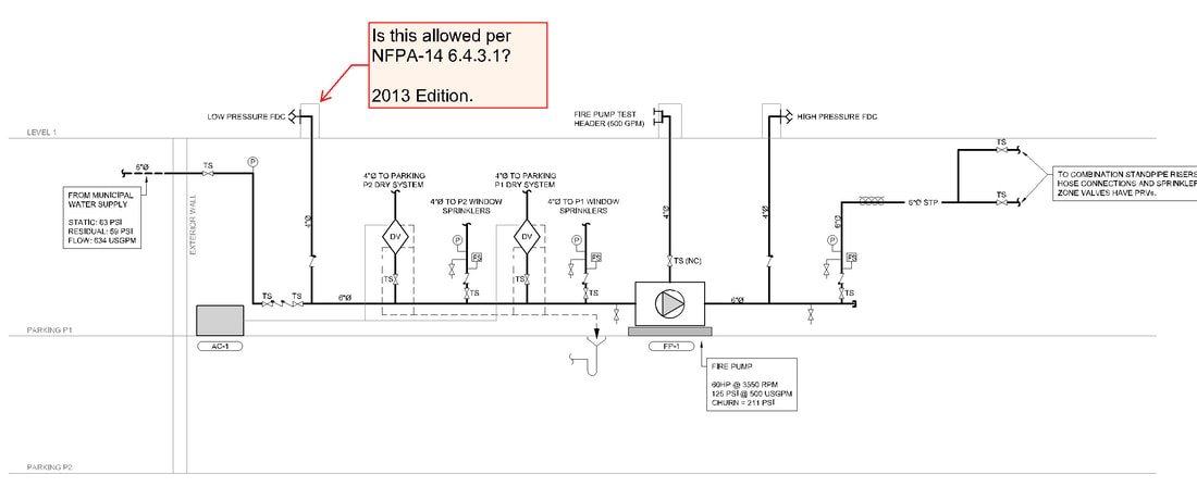 Questions: 1. Can you have a FDC serving the low pressure zones as shown on the suction side of the pump per NFPA-14 6.4.3.1? 2. If not, how should the schematic be arranged instead? 3. What could happen if the Low Pressure FDC were pressurized as shown? This project was built under the 2013 editions of NFPA-13, 14, and 20. I am asking because I am beginning design of a sprinkler system for a 22 story high-rise. Thanks for your help. Sent in anonymously for discussion. Click Title to View | Submit Your Question | Subscribe Is it code-mandated to have two control valves in the fire pump bypass piping?
Sent in anonymously for discussion. Click Title to View | Submit Your Question | Subscribe AHJ is requesting the design curve for the fire pump to be 5% lower than the pressure limiting driver (PLD) set pressure to account for the tolerance allowed NFPA 20-2019 Section 6.2.2.2 "When operating below the rated speed in a self-regulating mode, a self-regulating variable speed fire pump unit shall maintain the discharge pressure within 5 percent of the set pressure."
Is this an appropriate application for this requirement in NFPA 20? Sent in anonymously for discussion. Click Title to View | Submit Your Question | Subscribe I have wrote up several pump sensing line locations where they tap into the system. I understand it that they need to be be install between the discharge check and discharge control valve.
A contractor keeps installing on the pump bypass and says it works fine. Is this compliant? Is there a downside to attaching to the bypass? Thanks in advance. Sent in anonymously for discussion. Click Title to View | Submit Your Question | Subscribe I am a President of Board of a 4-story condo building. The building was built in 1982 and is concrete block. We received permission from fire marshal several years ago to remove all our fire hoses. The fire department told us that if there was a fire they would not use them. They would hook up to the FDC in front of our building. My question is - what is the purpose of the building's fire pump, and can we petition to also have it removed? 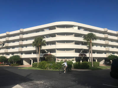 For multi family buildings, I am being told that for a 4-story building, normally the fire pumps are only 15HP because the standpipes are pressurized by the fire trucks.
My understanding of NFPA 20 is that it would still be required to have a correctly sized fire pump without considering the size of the pump on the local fire trucks. Is this an industry norm that is allowed by certain AHJ’s or is there code related to multi family that I am missing? Sent in anonymously for discussion. Click Title to View | Submit Your Question | Subscribe Would we still be required to conduct a forward flow test if we have a fire pump downstream and it's tested annually?
Thanks in advance. Sent in anonymously for discussion. Click Title to View | Submit Your Question | Subscribe Had a review comment come back and needed to clarify. I have a 14-inch city main with an 8-inch tap to a backflow in a pit. It then runs to four hydrants, and then turns into the building supplying a fire pump. The flow test at the hydrant near the tap (#1 on image below) was 49 psi static, 47 psi residual at 920 gpm. The flow test at a hydrant nearest the building (#2 on image below) was 49 psi static, 39 psi residual at 750 gpm. 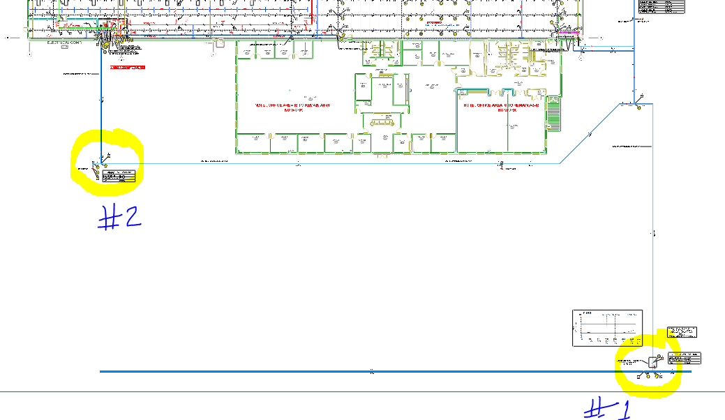 The 95 psi @ 1,500 gpm pump in the building is running the underground dry. The plot curve shows 20 psi at 2,100 gpm, however the pump rep said he barely got 500 gpm at 9 pitot and had to shut it down as the gauges went below 20 psi and air was starting to come out of the 2-1/2" hose valves.
This is a mystery to us - we have five different flow tests all ranging from 750 gpm to 1,060 gpm at 40-32 psi residual. Why would the pump be pulling the underground so low? They checked all the valves and rebuilt the backflow in the pit. Water meter is good as well (per the utility department). Looking for suggestions. Thanks in advance. Sent in anonymously for discussion. Click Title to View | Submit Your Question | Subscribe Can a floating dock standpipe with hose valves in the ocean be ran with PVC pipe?
NFPA 307 doesn’t go into detail about materials used but reverts back to NFPA 20, 22 and 24. This is in Florida. The AHJ wants it full of water so I have to issues, it’s too heavy to mount on the side of the dock, it’s not very big and it will be in the water or very close with high tide, so corrosion is inevitable. Is there anything stating Schedule 40 or 80 PVC is listed or acceptable for such use? Sent in anonymously for discussion. Click Title to View | Submit Your Question | Subscribe I have a project with Miscellaneous Storage of Class I commodities up to 12'-0" and Group A plastics up to 5'-0".
The water supply is a tank fed from a well. Based on NFPA 13-2016 Table 13.2.1, I designed to Ordinary Hazard Group 2 with a 90 minute duration of available water. My original demand was 57 psi at 385 gpm. Our pump supplier provided a vertical in-line pump rated to 80 psi 400 gpm. The client is now unhappy about the volume of water being required so they are removing the Group A plastics from their building so we can calculate to OH I with the new demand being 41.5 psi at 304 gpm. We have already installed most of the system and the pump is ready to be delivered soon. Is it okay to have an oversized pump? Can it be limited to a smaller flow to accommodate the new demand? My worry is that it will flow at the rated capacity and if we are sizing our tanks 10,000 gallons less than originally planned we would run out of water. Sent in anonymously for discussion. Click Title to View | Submit Your Question | Subscribe We have a building with an Extra Hazard Group 1 in a fairly rural location. We have an Electric, Diesel and Jockey (electric) pump system.
We had our diesel go out, sent away for repairs. What are the requirements for just having just electric in place? My concern is is the fire department cuts power if they come on site for industrial fire, or lose power due to weather, then we would have no suppression in service. The fire department can provide 1,500 gpm at 100 psi from a Type 1 engine through the FDC, (so 750 gallons). We have a pond to draft from. What would be the considerations? Amount of water available? In the event of power loss, the size of the FDC versus the size of the riser (a 6-8" dry pipe valve)? What would realistic attack line demand be for a hydrant/hose line? Can you think of anything else I'm not thinking of? Thanks in advance for the help! Sent in anonymously for discussion. Click Title to View | Submit Your Question | Subscribe Can a flow meter be installed in test header piping?
This is the first time I've ever seen this installation. Thanks. Sent in anonymously for discussion. Click Title to View | Submit Your Question | Subscribe Is there a specific location requirement for a fire pump test header? NFPA 20 states that the header must be installed on the exterior wall, and outside the fire pump room. Does this mean that the test header cannot be installed in the fire pump room? Additionally, can the test header be directly connected to the pump discharge flange as shown in this photo? 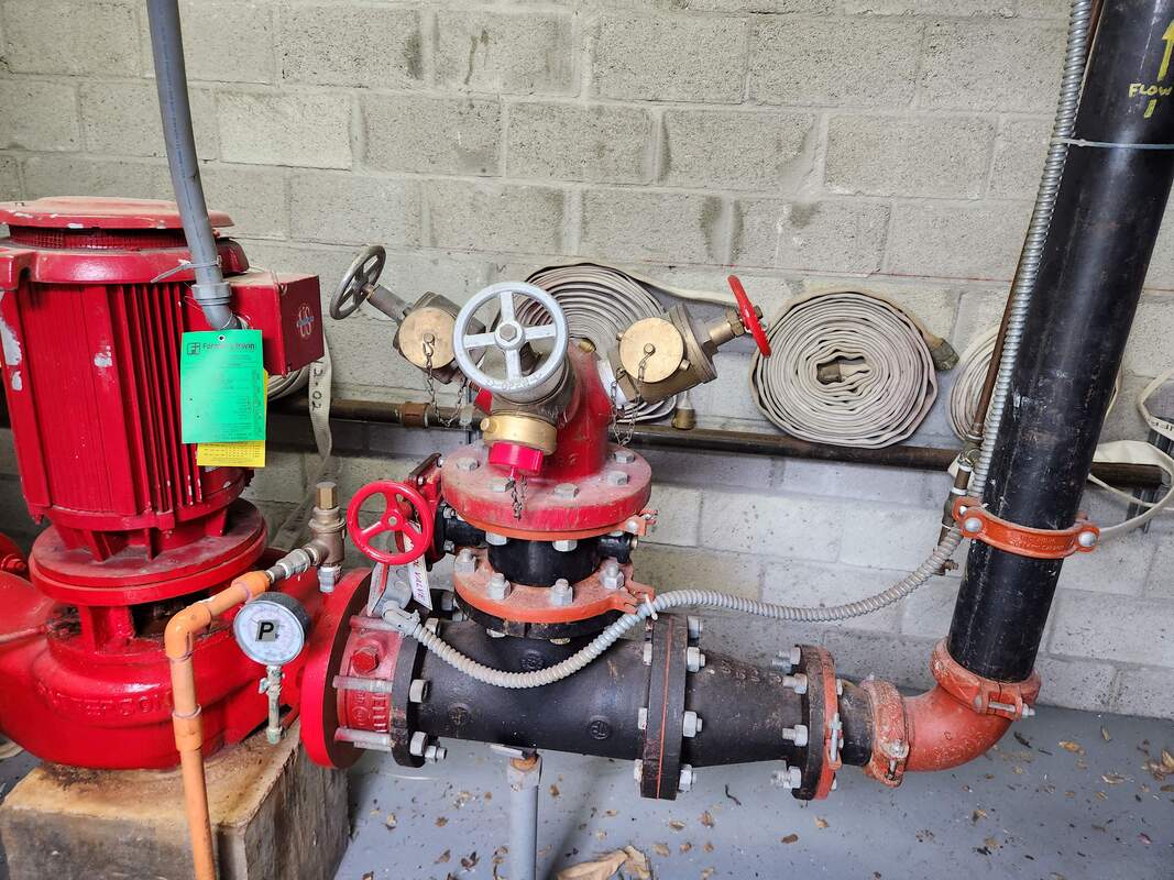 I have never seen this type of installation before. Thanks in advance.
Sent in anonymously for discussion. Click Title to View | Submit Your Question | Subscribe When is a fire pump pressure relief valve required?
Sent in anonymously for discussion. Click Title to View | Submit Your Question | Subscribe We have a case where two (2) x 2,000 gpm existing electric fire pumps (primary duty pumps) are available.
Now, the system design demand is increasing from 4,000 gpm to 12,000 gpm due to a scope change, so we are bringing in new electric fire pumps (as primary/duty) to meet the higher demand. All new fire pumps could be either four (4) x 2,000 gpm or two (2) x 4,000 gpm towards meeting the 12,000 gpm system capacity. All performance test curves are checked for all existing fire pumps; they are almost new and meeting the required residual pressure at 2,000 gpm and their performance is close to matching the original equipment manufacturer curves; so these existing pumps need to be retained. Now we do have space constraints, so we'd like to use the two (2) x 4,000 gpm pumps, and their pressure characteristics would be the same as the existing pumps. Would NFPA 13/20 (and any other relevant NFPA standard here) permit two different pump capacities for the system? Would having different pump capacities be concerning, or cause issues? Is there anything else we should be considering here regarding the capacities? Thanks in advance. Sent in anonymously for discussion. Click Title to View | Submit Your Question | Subscribe I have a unique quandary that I haven't run into before. We have an overperforming fire pump.
It was factory tested, we have a factory performance curve of 68 psi churn, 52 psi at 500 gpm (100%), and 35 psi at 750 gpm (150%). Once it was field installed, we were 1-3 psi over on Churn, 50%, and 100%, but +10 psi on the 150%. We had a net pressure of 45 psi at the 150% test when, based on the factory curve, the net should have been 35 psi. We checked the nameplate for the match, nameplate for the expected pressure at 150%; they all match. The supply for the test in the field got pretty low (about 25 psi suction at 150% flow). The only unique thing I can see about this setup is that we have a very tight room and had to meet a military spec to flow through the flowmeter and both run outside as well as back to the recirculation. As a result, the path from the pump discharge to the outside has to navigate through nine (9) elbows in order to get enough clearance upstream and downstream for the flowmeter in this very tiny pump room. Could a test header with that many bends be affecting the net pressure on the 150% test? Is this considered a failure? As this is military, it'll be by the book and I'm concerned that an overperforming pump might set up future tests for failure if I can't identify why it would be overperforming at the 150%. Thanks in advance! Sent in anonymously for discussion. Click Title to View | Submit Your Question | Subscribe We have a project and have gotten into an internal debate. The project has four diesel fire pumps in one pump house.
During testing, are we allowed to run all four at the same time? Or do we need to run each separately as we do normally to reduce the chance of blowing out a main? Anyone have insight on this? Thanks in advance. Sent in anonymously for discussion. Click Title to View | Submit Your Question | Subscribe Where does NFPA 20's jurisdiction end?
Is it possible to have pressure reducing valves in a suppression system, downstream of a fire pump? NFPA 20 seems to not allow for that, but does NFPA 20 apply downstream? If so, how far? In the standard it says up to a last control valve or something like that - what control valve(s) is it referring to? Thanks in advance. Sent in anonymously for discussion. Click Title to View | Submit Your Question | Subscribe When would you recommend replacing an existing fire pump?
I am working a project where we are renovating a large hotel and the diesel fire pump in the basement is dated 1994. I am aware there is a lifespan but with proper maintenance they can probably operate just fine for a long time. Is 30 years when you would begin to suggest replacing that piece of equipment? Should I make the suggestion to the client that it is best to replace and have them make the final call? Thank you. Sent in anonymously for discussion. Click Title to View | Submit Your Question | Subscribe NFPA 20 dictates the number and size of hose valves according to the pump rating, but is there any specific requirement on how many are to be used during testing?
How is that determined? Sent in anonymously for discussion. Click Title to View | Submit Your Question | Subscribe Is there any code that sets a specified elevation for the the Fire Pump Test Header above outside grade?
Sent in anonymously for discussion. Click Title to View | Submit Your Question | Subscribe |
ALL-ACCESS
SUBSCRIBESubscribe and learn something new each day:
COMMUNITYTop June '24 Contributors


YOUR POSTPE EXAMGet 100 Days of Free Sample Questions right to you!
FILTERS
All
ARCHIVES
July 2024
PE PREP SERIES |
 RSS Feed