
|
Had a review comment come back and needed to clarify. I have a 14-inch city main with an 8-inch tap to a backflow in a pit. It then runs to four hydrants, and then turns into the building supplying a fire pump. The flow test at the hydrant near the tap (#1 on image below) was 49 psi static, 47 psi residual at 920 gpm. The flow test at a hydrant nearest the building (#2 on image below) was 49 psi static, 39 psi residual at 750 gpm. 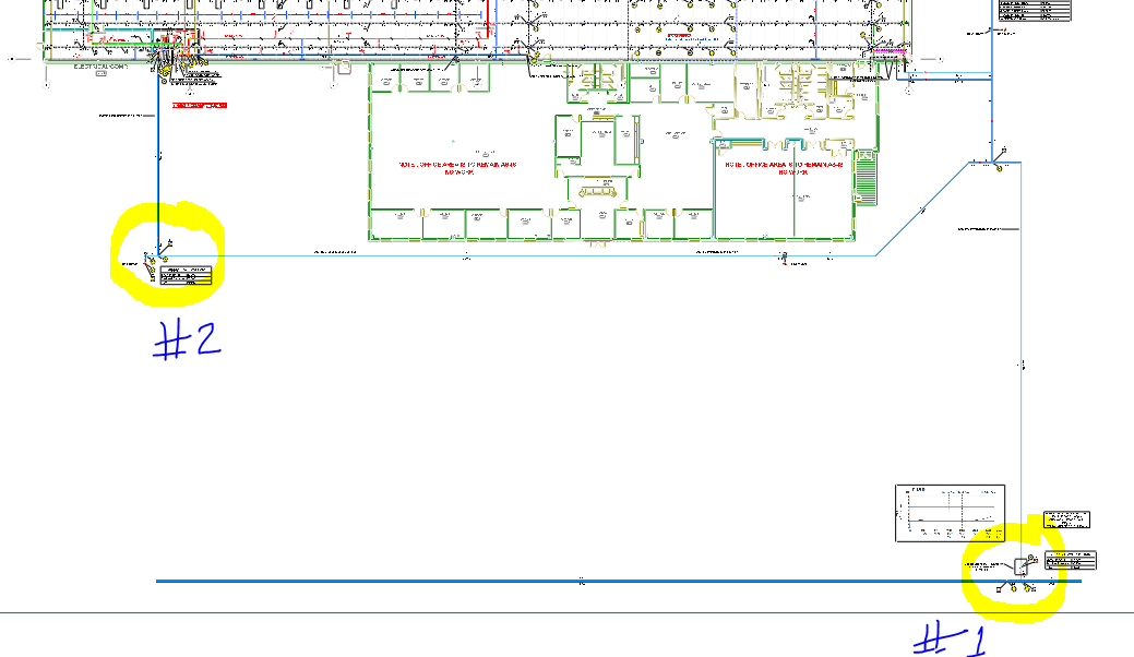 The 95 psi @ 1,500 gpm pump in the building is running the underground dry. The plot curve shows 20 psi at 2,100 gpm, however the pump rep said he barely got 500 gpm at 9 pitot and had to shut it down as the gauges went below 20 psi and air was starting to come out of the 2-1/2" hose valves.
This is a mystery to us - we have five different flow tests all ranging from 750 gpm to 1,060 gpm at 40-32 psi residual. Why would the pump be pulling the underground so low? They checked all the valves and rebuilt the backflow in the pit. Water meter is good as well (per the utility department). Looking for suggestions. Thanks in advance. Sent in anonymously for discussion. Click Title to View | Submit Your Question | Subscribe
19 Comments
Pete H
3/6/2024 06:34:00 am
Random question:
Dan Wilder
3/6/2024 06:49:13 am
1. Are those flow tests being done with just a single 2½" outlet? You're not getting the entire picture of the supply when the test results are only providing 50% of the requirements. Retest with multiple outlets (either 2-2½" outlet, the pumper connection, all 3 together, or additional outlets on additional hydrants). Also, try to get as close to 2250GPM as possible, at a minimum the rating of the pump or the system demand whichever is greater.
James Phifer
3/6/2024 08:12:15 am
We had a similar experience once. Turns out there was a 2x4 stuck in an underground elbow, restricting the flow. We ran a video camera thru the pipe to discover this.
Jesse
3/6/2024 08:13:30 am
This one's perplexing, and truth be told; I love mysteries like this.
Greg
3/6/2024 08:15:54 am
Air...air coming out of the hose lines in the middle of the testing, after you achieved flow ?
Chris
3/6/2024 08:31:16 am
Test #1 as identified above doesn't seem to be pulling enough water (as Dan said above) to be worthwhile data. Based upon the flow test results from the hydrant nearest the building, calculations indicate that you could expect a flow rate of 1,332.8 gpm at residual pressure of 20 psi. In comparison, looking at the flow test results from the hydrant near the tap, calculations indicate that you could expect a flow rate of 3,898.8 gpm at a residual pressure of 20 psi. The reduction in available flow to the downstream fire hydrant indicates why you are unable to achieve the flow necessary for the peak load of the fire pump. In fact, if you were to run the test all the way down to a residual pressure of only 5 psi in the underground main, you would only achieve a flow rate of 1,669.3 gpm, well below the 2,250 gpm that you are hoping for. If each valve indicates that it is open, I recommend using a camera to explore the internal condition of the underground main to check for obstructions as James described above.
Jack G
3/6/2024 09:44:12 am
Not being able to read the plan is a problem.
Jack G
3/6/2024 09:57:10 am
If it turns out that high excess pressure is being relieved— try recirculating it back into the suction ( with a small relief valve- 100 gpm , to make sure relief line doesn’t overheat)
David
3/6/2024 09:49:59 am
Based on test #2 you only have 1333 gpm available at 20 psi. I think the others are on the right track and you have a valve not fully open or an obstruction in your piping. I would also conduct another flow test, opening a sufficient number of outlets to verify you can get at least your rated pump capacity.
Eric R
3/6/2024 10:03:35 am
A useful way to check for closed valves or other obstructions is to perform a flowtest from the fire pump test header while flowing through the pump bypass assembly (I'm assuming you installed one) with the fire pump discharge control valve closed.
Jack G
3/6/2024 10:12:23 am
Another scenario is the water company rules and regulations.
Jack G
3/6/2024 10:19:01 am
Also— flow tests are not accurate beyond the point of their measured flow. The flow test in this scenario should have been 2250 gpm plus domestic water added to it.
Jack G
3/6/2024 10:30:20 am
Question — right side of sketch— 2 lines- one dark blue the other light blue- and red dots in those 2 lines and in loop line above and below it !
Jack G
3/6/2024 10:40:34 am
If the red dots are arrows, it would appear that you are recirculating the pump discharge into the underground loop than loop to suction . Just making a circle—- not a proper arrangement. 3/6/2024 10:39:22 am
I would place a gauge before the Backflow
Glenn Berger
3/6/2024 10:45:48 am
When conducting a fire hydrant flow test, you need to know what the anticipated facility demands will be and then test to ensure that the requirement can be met with actual flow test data. Never count of the extension of the plotted line as a guarantee of anticipated flow rate.
Let's start with the basics
Anthony
3/14/2024 09:47:21 am
Your hydrant tests make sense given your pipe sizes and Leave a Reply. |
ALL-ACCESS
SUBSCRIBESubscribe and learn something new each day:
COMMUNITYTop June '24 Contributors


YOUR POSTPE EXAMGet 100 Days of Free Sample Questions right to you!
FILTERS
All
ARCHIVES
July 2024
PE PREP SERIES |
 RSS Feed