
|
|
When coming out of a pump room with underground feed which then connects to an underground loop with a bullhead tee, are isolation valves required on the bullhead tee?
Sent in anonymously for discussion. Click Title to View | Submit Your Question | Subscribe
8 Comments
We are inspecting an existing fire sprinkler building for an upgrade to an Extra Large Orifice (ELO) system.
We performed a hydrant flow test and noticed a 14 psi static loss between the hydrant, 185-ft of 8-inch ductile, 2 elbows and 8 feet of elevation rise to the supply side of the RPZ backflow preventer. We recorded 73 psi at hydrant and 59 psi at the number 1 test cock on the RPZ while static. I spoke with the water authority and they confirmed no meter or check valve on the 8" fire line; it is straight into the valve room plus 2 elbows. The building is 20 years old and the pump test provided 120% of rated capacity. Any idea how the static pressure inside the building is 14 psi less? Sent in anonymously for discussion. Discuss This | Submit Your Question | Subscribe I've been seven years in the chair, and the most thankless job I encounter on every project is - reviewing the site utility plan and picking it apart.
I've now made my own rule that I will only point the civil engineer's mistakes once, early in the project, and when it comes time to stack the riser, pressure test, etc, all I can say is "I pointed that out to you on Aug 11 2020 email." Am I going about this the wrong way? SHould I even be investing energy into correcting the engineer with the stamp? Recent example is a two story building with concrete tees. We're adding third and fourth floors from new structural members. The underground man took the site utility and started digging. Check valve was exposed above ground (supposed to be in pit) and the FDC was connected to the underground on the system side of the backflow preventer. Now he has to dig it up, cap the tee after the backflow preventer, and run it around and inside the building. The job requires a small pump (CL1 manual wet standpipe), and the underground man wasn't happy. All I was doing was point out wrong installations before it was too late. I'm always left thinking, "this isn't even in my scope of work, but it affects everything downstream." Sent in anonymously for discussion. Discuss This | Submit Your Question | Subscribe We have an account that failed the five year FDC hydrostatic test. The Fire Department Connection is a remote, freestanding FDC. The Fire Marshal is claiming that there is no leakage, however, will not give a pass or fail.
NFPA 25 (2017) and others reference hydrostatic tests. 6.3.2.1 hydrostatic test 200 psi for 2 hrs or at 50 psi in excess of the maximum pressure where maximum pressure is in excess of 150 psi every five years. (manual standpipe systems and semi-automatic dry standpipe systems, including piping in the FDC) Annex 6.3.2.1* that mentions a minimum leakage existing under test pressure. Section 13.8.5 FDC five year hydrostatic testing shall be tested at 150 psi for 2 hrs. There is no mention of minimal leakage allowed. What is this allowable leakage? NFPA 24 (2010) Private Fire Mains & Their Appurtenances Section 10.10.2.2.1 requires 200 psi or 50 psi in excess of the system working pressure whichever is greater and maintain that pressure at +/-5 psi for 2 hrs. Is that my allowable leakage, so that if we lose less than 5 psi or gain no more than 5 psi for 2-hours, that we pass? Wasn't sure if the existing 5-year hydrostatic for underground has leakage that is measured differently from an inside hydrostatic test. Submitted anonymously and posted for discussion. Discuss This | Submit Your Question | Subscribe Is there a standard spacing for private fire hydrants?
No applicable code for this project, but looking for guidance in what would be common under NFPA 24, NFPA 1 / 101, and/or the IBC. Thanks in advance. Submitted anonymously and posted for discussion. Discuss This | Submit Your Question | Subscribe What is the residual pressure and flow require for both public and private fire hydrants?
Submitted anonymously and posted for discussion. Discuss This | Submit Your Question | Subscribe Many sprinkler systems in our area (I'm a fire marshal) have aboveground pipe installed by a fire sprinkler installer and the underground installed by an underground pipe contractor. NFPA 24 requires a minimum flow rate from underground pipe in order to remove rock and debris from the underground pipe.
Many of the underground contractors simply open up the pipe and wait until there's consistent clear water and/or stop hearing the rocks ping around. There's no measurements taken for the underground flushing and when I ask for them to verify the flow rate I get blank stares. Is there a way to tell just by static pressure in the area if opening up the pipe flange is enough flow to satisfy the underground flushing? Or is there a measurement I should be seeing to verify the flow rate? Thanks in advance. Submitted anonymously and posted for discussion. Discuss This | Submit Your Question | Subscribe NFPA 24, Section 7.1.1.2 (2016 Edition), states that control valve shall be installed in each hydrant connection. What is the purpose of this control valve, other than facilitating maintenance? Would this be considered a "control valve" per NFPA 24 3.3.3, and does this have to be a post-indicating type valve? 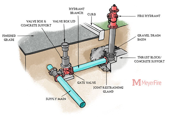 Common hydrant arrangement for illustration purposes. Based on my limited understanding, this control valve is just a post-indicator valve/isolation valve which is for shutoff when there is an impairment downstream. I'm trying to get a better understanding of its purpose. Thanks in advance.
Submitted anonymously and posted for discussion. Discuss This | Submit Your Question | Subscribe Please can someone give some information regarding the filling speed of a empty pipeline to a sprinkler line?
In my case there was water hammer in a 6” line, The 16” firewater line was under 175 psi pressure and the opening time was 9 seconds. Is 3 feet per second more realistic? Or is there a NFPA standard that addresses this? Thanks in advance for your support! Posted anonymously for discussion. Discuss This | Submit Your Question | Subscribe Have a project which has a remote fire department connection outside of the main building. The fire department connection has its own dedicated feed that goes from the remote FDC, underground, up into the building, where it connects to the fire sprinkler riser downstream of the backflow preventer.
The check valve for this line is required to be inside the building, so the main between the FDC and check valve in the building is intended to be dry. NFPA 24 (if that applies) allows PVC for underground water service in its table of permitted pipe types. NFPA 13 specifically states that galvanized steel is permitted to be used between the FDC and the check valve serving the FDC. I can't see where NFPA 13 would mandate pipe types for this arrangement. Is this underground FDC feed allowed to be PVC? Posted anonymously for discussion. Discuss This | Submit Your Question | Subscribe I haven't had any experience doing site calculations before, but I'm curious how it works from a practical standpoint. Fire Flow is required by the International Fire Code here locally, and there's guidance (albeit not formally adopted) in Appendix B of the IFC for a total demand. Additionally, there's hydrant spacing requirements for any particular building, and guidance on how far the hydrants can be from a building.
In order to determine how the hydrants are fed (dead-end vs. looped and size of pipe), are there specific flow and pressure amounts that each hydrant has to be calculated at? Is it similar to a standpipe calculations where each hydrant has to have a specific flow? I'm not performing the design work myself, but I'm just curious how that is typically done and pipe size determined. Posted anonymously for discussion. Discuss This | Submit Your Question | Subscribe I have a project that is Seismic Design Category D. I'm researching and I thought there were requirements that stemmed from the Northridge Earthquake in 1994 related to the limiting the height/length of the sprinkler service entry.
Is there a 5-foot limit from the underground to the riser for seismic projects? Posted anonymously for discussion. Discuss This | Submit Your Question | Subscribe What is the best way to cut in to an existing underground line that may have a thrust block at the end?
We are doing a project that has scope to retrofit an 8" backflow into an existing approximately 200' of 8" underground. There is an existing detector check valve in the line which will be removed. Because of the age of the building and underground (about 30 years old) it is assumed the piping has a thrust block at the end. But with cutting into the line and adding a couple 90 degree elbows to get the backflow above ground there is fear that the line may slip back to the water main because the thrust block at the end of the 200' run is no longer holding the entire line in place. We are planning to add a thrust block to the new 90s, but the issue is that there is only a shut off valve that is in the straight line of the 200' of pipe. If we shut that valve, there will still be pressure on the front side of the valve and when we cut into the pipe, the pipe may slip. Any suggestions on securing the pipe on the supply side of the new backflow or limiting the pressure prior to the concrete being poured on the elbows for the backflow? Posted anonymously for discussion. Discuss This | Submit Your Question | Subscribe One of the frustrating non real-world things in consulting is that on the contracting side, 99.9% of the time we start at flange inside the building. Red-line the contract if needed, or work out an informal deal with the underground contractor.
On the consulting/engineering side we have this whole underground spec section, just for five-feet out, including tracing wire and tape, testing offsite soils, soils disposal, shoring, compaction, size of rock, etc. I understand the civil engineers will only take it to five feet. I’ve asked my people why we can't just match reality and just start inside the building? I am told if we did there is this 5-ft. gap that has to be claimed by someone (despite what is done in reality). Have you addressed this in your experience in any way? I am wondering how others deal with it. On the contracting side we all just made it happen. On the consulting/paperwork side, it’s hard to make the paperwork match reality. Do you even seen thrust block calcs submitted from anyone since it is part of the imaginary five-feet out? Sorry, ranting a bit, it came to mind again today because I have constructability comments from the architect that recognized that in this particular case, the AHJ permit covers from the flange, their solution is to have my spec cover the entire fire line. I’m not comfortable with that. Posted anonymously for discussion. Discuss This | Submit Your Question | Subscribe Do underground gate valves for fire main water supplies have to be monitored and supervised?
Posted anonymously for discussion. Discuss This | Submit Your Question | Subscribe For straight pipe couplings, are thrust blocks required, or is it only at any change of direction in the piping? It seems as though restrained joints seem to be common now, but the question came up when using thrust blocks instead of the restrained joints.
Posted anonymously for discussion. Discuss This | Submit Your Question | Subscribe |

ALL-ACCESS
SUBSCRIBESubscribe and learn something new each day:
COMMUNITYTop March '24 Contributors


YOUR POSTPE EXAMGet 100 Days of Free Sample Questions right to you!
FILTERS
All
ARCHIVES
April 2024
PE PREP SERIES |
 RSS Feed