
|
While you're here, we've had great discussions on tackling challenges with bid specifications. I'm very encouraged by the response and I'd like to move things forward with drafting an open, easy-to-digest fire sprinkler specification. My next question for you is - in an ideal, simple, concise fire sprinkler specification - what do you want to see addressed? If you're bidding on a job - what is it that you want to see adequately addressed in the specification? Allowable types of pipe? Types of sprinklers? Use of flexible drops, or other fittings? System types? What is it that you look for that is can't miss in a quality fire sprinkler specification?  Let me know below and we'll do our best to work it in to a new open fire sprinkler specification.
When you conduct a hydrant flow test, how precise is your resulting measurement? Let’s say a flow test summary shows 82 psi static, 54 psi residual at 956 gpm. Is it really 956 gpm?  Well, no, of course – but 956 is the best resulting estimate of the flow test with the information and measurements we have at hand. It’s where the dial best predicts. But how precise is that measurement, really? Are we certain that it’s 956 gpm and not 957 gpm, or 960 gpm, or 1,000 gpm? Now of course, a hydrant flow test is a point-in-time measurement. It’s not representative of daily fluctuation or seasonal fluctuation. Let’s save that discussion for another time. What I’m really interested in is when we take a flow test or run a pump test, how accurate are our results, really? SIGNIFICANT DIGITS The concept of significant digits is one simple way avoid suggesting a higher level of precision than a measurement justifies. In other words, if our flow test results said 956.21 gpm, we’re suggesting, based on the decimal placement that we actually know that the value is not 956.4 gpm; it’s instead between 956.2 and 956.3. That’s a level of precision that is suggested by significant digits. Technically, if we had a pitot gauge reading of 9 psi during a flow test, then we would have one significant digit. Using one significant digit is very problematic in flow test results. Q=29.84×C×d²×√P In this flow conversion formula above (the Freeman Flow Formula), we take we take pitot pressure (P), opening diameter (d), and the Coefficient of Discharge (C), to get a resulting estimate of flow through an opening. The problem with using the significant concept is that a pitot reading of a single digit value would mean that we round our resulting flow would yield one significant digit. LOW PITOT MEASUREMENT NFPA 291 actually recommends that pitot readings less than 10 psi should be avoided, if possible. That would mean flowing fewer outlets to get a higher pitot reading to avoid inaccurate readings. So, at least in theory, three 2.5” outlets with a C-factor of 0.90 and a pitot of 9 psi each would result in a flow estimate of 1,511 gpm being rounded to – what – 1,000 gpm or 2,000 gpm? The concept of ‘significant digits’ here would result in massive rounding error. This line of logic is where I was really curious about our flow test results – or really any measurement of flow, such as pump testing. How precise are our measurements? BIG GAUGES, SMALL TICKMARKS If you’ve tried to take a close reading and nitpick the difference between 96 and 97 psi on a 300 psi gauge – that can be extremely difficult to do. Yet, at least in the case of fire pump testing, that result can be the difference between passing or failing a fire pump test. 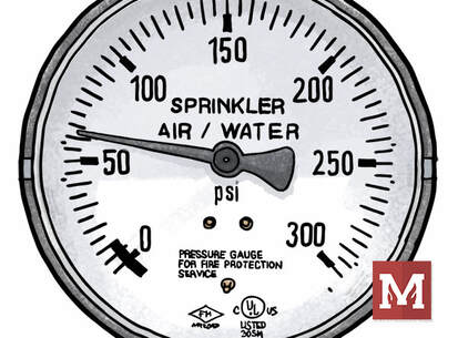 How precise can we read a higher-range gauge with small or grouped tickmarks and a small-diameter face? If you don’t think that’s a high-stakes proposition, then I’d invite you to wrap up final acceptance testing on a federal project with every stakeholder present and watching. It can be high stakes. Perhaps the more appropriate way to understand precision is by doing error propagation on this conversion. Error propagation is a sore point for me, as I pretty much failed every physics lab in college that required it. Time to shed those demons. If you’re not into math, skip ahead to the summary to see where I ended up. I want to show my work here as I haven’t seen this done and I’m very much for transparency and getting feedback, especially when I venture a little beyond my own fenceposts. ERROR PROPAGATION FOR FLOW TEST CONVERSION Error propagation is a fancy way to describe the reliability of the resulting calculation. How precise is the result? That’s what we want to know – and knowing so can help us make more informed decisions in our assessments.  A formula with multiple variables, where each have their own uncertainty, the overall uncertainty depends upon how each variable affects the final result. In other words – if I’m not exactly sure about the numbers I’m putting in, how unsure should I be about the answer I get out? IMPACT OF DIAMETER VS. PITOT PRESSURE In this equation, a percentage error in measurement of a diameter could have an outsized effect on the resulting flow since diameter is squared. To run an error propagation on a formula involving variables which are multiplied together, we square the relative uncertainty (change in a measurement divided by the measurement), square them, add them together, and square out the result.  EXAMPLE: 60 PSI GAUGE So, let’s say we ran a flow test where we were certain in the Coefficient of Discharge (0.90), we measured and were confident in the diameter of 2.5 inches (within a 1/16th of an inch), and took a pitot reading of two side outlets each at 8 psi using a 60 psi gauge with 1% accuracy. Practically speaking, that’s a very reasonable amount of tolerance of a normal hydrant flow test or fire pump test. With those results, we would calculate a total flow estimate of about 950 gpm.  How precise is that flow? 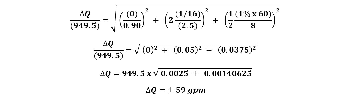 (Error in flow test reading measuring opening within 1/16” and pitot with 60 psi gauge) So, with a variation of + 59 gpm, our resulting flow estimate would be 950 gpm + 59 gpm, or a resulting range of between 890 gpm and 1010 gpm. That’s a pretty wide variation – and it’s certainly a lot wider than I would have expected considering we’re using a 60 psi gauge with 1% accuracy. EXAMPLE: 100 PSI GAUGE What would happen if we used a 100 psi gauge with 1% accuracy?  (Error in flow test reading measuring opening within 1/16” and pitot with 100 psi gauge) EXAMPLE: 300 PSI GAUGE Taken to an extreme – what if we used a 300 psi gauge to measure pitot? A bad idea for sure (it’s nearly impossible to read sensitive low amounts, and likely in the least-accurate portion of the gauge. But just for kicks:  (Error in flow test reading measuring opening within 1/16” and pitot with 300 psi gauge - which we would never recommend doing) EXAMPLE: 60 PSI GAUGE WITH IMPRECISE DIAMETER Now, what if we were less confident in the actual inside diameter of the hydrant side outlet? What if we thought it was 2.5”, but only within an 1/8th of an inch? With our 60 psi gauge:  (Error in flow test reading measuring opening within 1/8” and pitot with 60 psi gauge) Yikes! Did you notice that? Even with a 60 psi gauge, if we only know the inside diameter within an 1/8th of an inch, it’s worse than using a 100 psi gauge. Knowing the precise inside diameter is important as it has a huge effect on the level of precision. HOW DO WE IMPROVE PRECISION? Based on the inputs – there are a few key ways to improve the precision of flow test readings when we use pitot gauges to estimate the amount of flow. I’m interested in writing more on this in the coming weeks, but there are a number of ways in which we can improve the precision of our flow testing and have more confidence in our results. #1 MEASURE THE OPENING SIZE First – and probably the most important based on our calculation – is to know the exact diameter of the orifice opening. If we are flowing out the side of an outlet, we actually need to measure, with precision, the inside diameter of that opening. As I’ve been told, not all inside diameters are equal. They depend on the exact make and model of a hydrant. I’ve made this mistake before and assumed all 2.5” side outlets are the same inside diameter. To improve precision, take a careful measurement of the exact inside diameter of the opening down to the 1/16th of an inch. Alternatively, using a factory-created attachment with a factory-milled opening will help define and make that variation go away. A known diameter with a very tight factory tolerance helps us reduce or eliminate this concern altogether. #2 USE SMALLER RANGE GAUGES In general, we want to use the smallest range for the gauge possible. Using a 300 psi gauge to measure anything within 0-30 psi is problematic. Not only is that a less-accurate range for a gauge (near the ends), it’s extremely difficult to read. The tickmarks just become too small to read well. Instead, we want to use the lowest gauge range that’s possible for the test. If we’re expecting results below 100 psi, can we use a 100 psi gauge instead of 200 or 300? If we’re measuring pitot and expecting values under 60, can we use a 60 psi gauge? Even a 30 psi gauge? The bigger the tickmarks and the smaller the range, the better we’re going to be able to see and read the results. 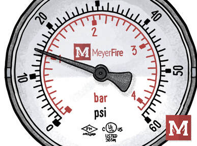 Using a lower-range scale gauge can lead to far-easier reading of the gauge, but also be within a more accurate range for the gauge itself. #3 LARGER-DIAMETER GAUGES
This goes against my “travel with small things” concept, but larger-diameter gauge faces are so much easier to read in the field. They cost more. They’re bigger. But man are they easier to pull values from. Again – on an important fire pump closeout with many people all watching – having nice clear results to prove the system works as it should helps. #4 USE CALIBRATED GAUGES For fire pump testing, NFPA 20 requires that all gauges undergo annual calibration testing and be accurate within 1 percent. (NFPA 20-2022 Section 14.2.6.1.2) For fire hydrant flow tests, that same mandate doesn’t necessarily apply. NFPA 291 is a recommended practice, and requires calibration within 12 months, but is not necessarily enforceable in the same way that NFPA 20 is. Now, if you’re on a federal project and NFPA 291’s “shoulds” become “shalls”, then there are enforceable teeth. But for private practice work, many flow tests are simply run with whatever gauge is on the truck that day. Using a calibrated gauge will obviously hone in for more precise measurement. #5 USE STREAM-STRAIGHTENERS NFPA 291 now specifically states a preference for playpipes or stream straighteners to improve the accuracy of readings. Not only do these address the precise opening sizes we talked about earlier, but they hold the pitot measurements in a fixed-in-place mounting position. This also means we should be measuring at exactly the right center-of-stream location. This is explicitly listed now in NFPA 291 (2022) Section 4.6.2. SUMMARY Doing a little error propagation highlights a few things about the measurement process in a calculated way. We can look at the accuracy of our input measurements an in turn, get a level of confidence about the resulting range of flow from those measurements. The more precise we are able to measure, the more confidence we have in the result – which is both an obvious ‘gut-feeling’ but can also be mathematically proven. YOUR TAKE I’m interested in your take. What are your tips for more accurate readings? What stories do you have about fire pump acceptance testing or hydrant flow tests in this regard? NEXT STEPS I’d like to venture down this rabbit hole just a little further. My next thought is to apply the error propagation concept into a quick calculator tool where you could see your error range yourself – and experiment with different situations. You might just find an error range based on your normal test equipment that could present your test results in a more appropriate and transparent way. That's TBD (to be developed). Thanks for reading – and, as always, for fighting the good fight. Have a great rest of your week. - Joe A couple weeks ago we updated the NFPA 13 shop drawing checklist with new references to the 2019 and 2022 Editions of NFPA 13. With the 2022 update, the NFPA 13 Committee revamped the list of requirements for “working drawings” in the 2022 Edition. It was pretty much gutted and rewritten. DOES A 2022 UPDATE CHANGE ANYTHING? What impact does this actually have for me or my team? Who uses the 2022 Edition right now? Well, perhaps no local jurisdictions have adopted the 2022 Edition yet. Perhaps that’s a few years away still. But what about US Federal work, which references the latest standard edition at the time of the job posting? Or large corporate or healthcare users who might mandate adherence to the latest codes & standards? Or, what if we’re just being prudent and looking to be ready to adapt when it is enforced? Well, yes then, it could have an impact on your process whether you’re creating the working drawings or reviewing them. Here’s the list of noteworthy changes to the working drawing list as I understand them. Please note that I’m far from a Committee member and it’s only my interpretation of the list. As this plays out in time, I’m sure plenty of gray areas will get sorted out in online discussions, informal clarifications, or code changes. 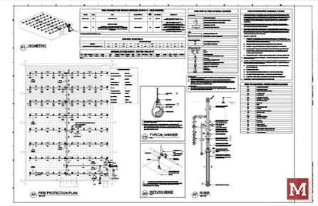 The list of shop drawing requirements went through an entire revamp with the 2022 Edition. #1 SHOW THE MEANS OF FORWARD FLOW (ADDED IN 2019) A means of conducting a forward-flow test has long been required, but historically overlooked or was possibly achievable by flowing out of a fire department connection or main drain (for very low hazards). We talked about the big change for a fixed means of forward flow that was introduced in 2019 and clarified in 2022. How does this affect shop drawings? Well, we now need to locate and identify the means of forward flow on the plans [NFPA 13-2019 Section 27.1.3(25) and 2022 Section 28.1.3(18)]. 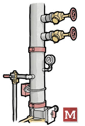 The location and labeling of the means of forward flow is required in the 2019 and 2022 Editions of NFPA 13. #2 THE BUILDING CROSS-SECTION WAS REMOVED If you’ve ever prepared or seen a random building cross-section on shop drawings (with no pipe or sprinklers shown), that’s because NFPA 13 had a requirement showing a full-height cross section that showed ceiling construction, protection for non-metallic pipe, and structural member information. This was a constant source of review comments, which does help clarify what’s going on, but is only a single slice of a building that otherwise could be very complex. In the 2022 Edition, the list goes away from the building cross section and instead requires identification and locations of major structural members [2022 28.1.3(11)], labels of Obstructed or Unobstructed where applicable [2022 28.1.3(11)], and ceiling heights labeled on the plans [2016 23.1.3(45), 2019 27.1.3(5), and 2022 28.1.3(9)]. From a matter of design and practicality, showing ceiling heights and structural members on the plans themselves helps us all communicate a bit better. Showing all the ceiling heights, structure, and Obstructed vs. Unobstructed with plan labels was something I incorporated a few years ago and helped me be more disciplined during design. It also beats out a single-slice section of a building that may or may not actually clarify how much of the building is being constructed. 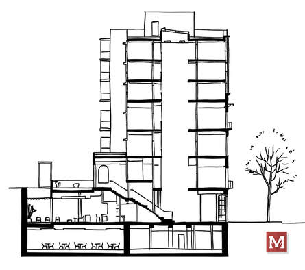 A building section that doesn't detail sprinklers or pipe, nor is at a position or scale that effectively communicates the relationship of structure, ceilings, and coverage - doesn't do a lot of good. It may not have been the original intent of NFPA 13 anyway. The NFPA 13-2022 Edition removed the requirement for a whole-building cross section but added plenty of labels and requirements to the floor plans to adequately address the original reason for inclusion. #3 LIGHTS, DIFFUSERS, AND OTHER CEILING FIXTURES Many bid specifications require that lights, diffusers and other ceiling-mounted devices (fire alarm, occupancy sensors, etc) be shown on sprinkler working drawings. Doing so certainly helps prove that the ceilings have been coordinated – or at least other systems considered. But now that’s been codified. In the 2022 Edition, Section 28.1.3(8) requires diffusers, lights, and other ceiling fixtures or major MEP equipment just above or below the ceiling be shown on the sprinkler working plans. This seems easy enough to require for a consultant – but for a sprinkler contractor, pulling in this information can be a chore – especially if the sprinkler subcontractor doesn’t get a full set of CAD plans to begin with. Hopefully, with this being codified, a sprinkler contractor’s request for CAD backgrounds on this information gets a little easier to push back up the food chain. 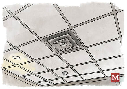 We know lights, diffusers, and other ceiling fixtures will be on a project. Now we're required to have them on sprinkler installation plans. #4 PLACARD INFORMATION Hydraulic Data Nameplate information has long been required to be shown on the working drawings, but now the hose demand, method of calculation, and total flow and pressure have been added to the list. This comes from the 2022 Edition, 28.1.3(23c). #5 OWNER’S CERTIFICATE INFORMATION NFPA 13 has long required that a signed Owner’s Certificate to be submitted with working drawings (1999 8-1.1.2, 2022 14.1.4, 2007-10 22.1.4, 2013-16 Section 23.1.4, 2019 Section 27.1.1.1(4), 2022 Section 28.1.4). Now, with the 2022 Edition, required information from the owner’s certificate is required to be shown on the plans [2022 28.1.3(14)]. This includes storage materials, storage heights, water supply information, and whether seismic bracing is required. This is discussed in more detail in 2022 Edition Section 4.2. 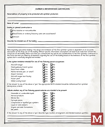 The Owner's Information Certificate has been a requirement to be included with working drawings, but now the required information from it is also required to be shown on plans, starting with the 2022 Edition. #6 DESIGN CRITERIA FOR EACH SPACE The 2022 Edition clarifies that design criteria for each room or space be shown on the plans, including hazard classification everywhere, and commodity classification, storage type, configuration, height, and packaging for storage areas [2022 Section 28.1.3(15)]. That’s often critical yet hard-to-find information for plan review. This clarification puts some teeth to requiring that information be shown on plans. #7 FLEXIBLE DROP INFORMATION The 2022 Edition introduces requirements to indicate corresponding k-factor, length, manufacturer, maximum number of bends, minimum bend radius, and model for flexible drops when they’re used [2022 Section 28.1.3(17b)]. While many designers already indicated at least some of this, having the maximum number of bends and minimum bend radius on the plans could go a long way in helping on-site inspection make sure that the install actually adheres to the design intent. Not a terrible idea. #8 MORE SEISMIC DETAIL The 2022 Edition requires more detail on several seismic bracing components. These include design angle categories, flexible coupling locations, locations of seismic components, maximum spacing, penetration clearances, and zones of influence all to be shown on the plans [2022 Edition Section 28.1.3(22)]. IMPACT FOR PLAN REVIEWERS The “working drawing” revamp in the 2022 Edition shakes up an area of the code that hasn’t changed much in some time. For plan reviewers, this is a welcome relief. Many of the updates and additions are simply requiring pockets of information that a plan reviewer needs to know for proper review, but is really difficult to surmise if they’re outside of the design development process. Having teeth to require that commodities and storage arrangements and Obstructed & Unobstructed be identified on the plan will go a long way in checking due diligence has been done in key areas. IMPACT TO DESIGNERS For designers? This could be a tall ask. There’s some major adjustment here. For designers who traditionally have been very thorough in plan preparation and documenting each step of the process, this will be more of a matter of simply sharing some of that documentation. For designers that may not have gone into this level of depth – there’s certainly going to need to be more time dedicated to the process. More time to ask the owner for input. More time to ask for more complete backgrounds for coordination. More time to document, label, and identify details on plans. It’ll take more time. If designers already feel crunched by design time budgets, then it’ll be be an adjustment for everyone. IMPACT TO ESTIMATORS For estimators? When the 2022 Edition (or later) gets enforced, plan on designers needing some additional time to take this on. Time adds for design will be greatest for buildings with storage, seismic projects, or jurisdictions who provide thorough review. There’s plenty of teeth to the the updated list, so it’s less of a “well these things are technically supposed to be provided in the spec” and instead “NFPA 13 requires this to be shown.” Less room to maneuver, in other words. TAKEAWAYS Personally, I like these changes. They allow for clearer communication of intent, which is the point of drawings in the first place. It’ll allow designers to be more thorough in their process. While that might sound contradictory (why would a designer want to be pushed to be more thorough?), many good designers lament that the pace and expectation for flying through design is too fast. Having NFPA 13 be the backbone of what needs to be submitted gives designers a tangible justification to do a more thorough (better) job. The NFPA 13 requirements can play the part of the villian, not the designer who’s trying to do things at a depth that they feel is needed. Hope you enjoyed the recap here, and that you have a great rest of your week. Keep up the good work. - Joe Last week we updated the NFPA 13 shop drawing checklist with references to NFPA 13 2019 and 2022 Editions. While code updates like this are traditionally modest, the NFPA 13 Committee revamped the entire list of requirements for “working drawings” in the 2022 Edition. It was gutted. We’ll expand on that more next week. This week I’d like to key in on one very impactful change that I think will affect many of us in how we design systems going forward. FORWARD-FLOW REQUIREMENT HISTORY A forward-flow test has long been required in NFPA 25 (dating back to at least 2002). The purpose of the test is to verify that a backflow preventer is capable of fully-opening in a fire – or at least to the extent that it allows enough water to flow to satisfy the sprinkler system’s demand. A means of conducting a forward-flow test has long been required, but not necessarily readily implemented. For many lower-hazard systems, it was a test that was possible by flowing out of a fire department connection or main drain. WHY NOT FLOW OUT THE FDC? White it was possible to do a forward flow through an FDC, this approach was never practical. I can’t stand on a high horse here – it was the approach I long used from a design perspective. It’s not practical because conducting a forward-flow test out of an FDC would typically require a system to be shut off, drained, check valve reversed, put back into service, tested, shut off, drained, check valve put back into place, and put back into service. And that was if the clappers on the FDC were removed or restrained in a way to allow enough water to pass through. It’s a tall ask. USE THE MAIN DRAIN? Flowing out the main drain could be a solution for forward flow, but practically speaking how much water can flow through a 2-inch main drain, especially if there’s an OH1 or OH2 demand? Do we have a way to verify how much water we’re flowing, so that we know the test passed? Some have used our own calculator to estimate the amount of water flowing through a main drain by using this orifice flow calculator - https://www.meyerfire.com/blog/a-new-fire-sprinkler-test-drain-flow-calculator That calculation is based on pressure flowing through an opening – either an orifice or pipe diameter – and doesn’t incorporate the losses that occur through the length of a main drain or the fittings along the way. It’s going to be too generous on the amount of flow coming through a main drain – which is good if we’re wanting to know how much water a plumbing drain needs to accept – but bad if we’re trying to prove forward flow based on it. I would suspect that a supply-side calculation (where the available pressure dictates the flow) through a fully-open main drain would be the best way to predict hydraulically how much flow a main drain could flow. If that’s well above the system demand (including hose allowance), then a main drain could be the means to flow. But a 2-inch main drain is very likely not an answer for forward flow for most systems. I’ll leave that discussion open – perhaps there’s a tool we could construct to account for main drain losses and perform that supply-side calculation. PERMANENT MEANS FOR FORWARD-FLOW Somewhat fortunately for those of us who like black and white guidance (myself included) –the NFPA 13 committee closed up the gray area in the 2019 Edition by requiring that an arrangement for conducting the forward flow test, at the minimum flow rate of the system demand (including hose allowance), would be provided “without requiring the owner to modify the system to perform the test.” This comes from NFPA 13-2019 Section 16.14.5.1.1. In the 2022 Edition, the committee went further.  A fixed means of forward flow, like hose valves on a test header or system riser, will become far more commonplace once the 2019 and 2022 Editions of NFPA 13 are adopted and enforced. A 2-1/2” HOSE CONNECTION FOR EVERY 250 GPM A test connection is now required for forward flow tests, where now a 2-1/2” hose valve is required for every 250 gpm (950 L/min) of system demand. This total flow must include the hose allowance where applicable. Generally, if there are interior hose valves, then this would need to get added in. So - an Ordinary Hazard Group I system that may have a demand of 270 gpm (with 250 gpm outside hose allowance), would still need two 2-1/2” hose valves for the forward flow test fixed in place downstream of the backflow preventer. For larger systems, or those with interior hose connections? We could be looking at three or more hose connections just for forward flow. This comes from NFPA 13-2022 Section 16.14.5.1.1. That’s a noteworthy change. For a code-minimum, sprinkler-system-only type of project, that’s a tangibly different cost and look to a part of the system. Does this have to be a test header on the outside of the building? Not necessarily, though that would be nice for future testing. Could the hose valves be on a riser in a room that has exterior access? Depending on the room and goals for the building – that could be reasonable. There are two provisional sections that allow existing hose connections to be used for the test (16.14.5.1.2), and other means to test are allowed “as long as the system doesn’t require modification to perform the test and is sized to meet the system demand.” The later comes from NFPA 13-2022 16.14.5.1.3. 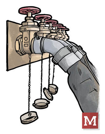 Is a fixed test-header on the exterior of the building required? No, but it could be convenient for future testing in areas where theft is less of a concern. HAVING TEETH
But in general – we don’t have a “use the FDC” workaround any longer. For those in IT&M, we finally have a sticking point to give an ability to do this test without tinkering with the system. For those in design, we finally have a magic section of code that we can show to justify providing a means of the forward flow test. For those in review and inspection, we have the teeth to enforce it. Hopefully, in the long-run, having systems tested for forward flow will identify backflow preventers aren’t functioning and we no longer have them in buildings ready to fail when a fire happens. Hopefully, this pushes buildings to a bit safer and helps us a be a little more confident in the system’s ability to fight a fire. SHOW ON WORKING DRAWINGS While the means is an installation question – NFPA 13-2022 Section 28.1.3(18) requires that working drawings locate and identify the means of forward flow. It’s no longer a “how do you plan to do this test?” type of comment and will soon be “show the location and label the means of forward flow, per 28.1.3(18).” MY FORWARD-FLOW STORY Are we really just testing the backflow preventer here? Well, yes. In part. But actually flowing an entire system demand tells us quite a bit. It means that our water supply is capable of flowing the full system demand, and all the pipe in-between the water supply and the backflow is also open-enough to flow the full system demand. I once had a project where a tap was made to the city supply main. It was a live tap or “hot tap,” where a drill punctured the side of the city main and a new 6” street valve was installed and our 6” underground came in and fed the building. It was a brand-new 3-story building that was going to have overnight guests. The tap wasn’t fully-made. In fact, as we found out later through a lot of cost and trouble, only a ¾” pilot drill bit made it through the city main. It wasn’t all the way drilled-in. Instead of a 6” tap, we had a ¾” tap. Static pressure to the building was fine. We could run a main drain test just fine (the residual dropped, but the main drain isn’t flowing all that much). Remember – the initial main drain test sets the threshold to check against in the future. We could flow the inspector’s test just fine. When we conducted the forward flow test and opened a couple 2-1/2” hoses – we had no water. No pressure at all. It wasn’t until we conducted the Forward Flow test that we knew there was a problem. Where it not for the Forward Flow test, we would have had a brand-new building, which, by all other measures we would have thought was designed and installed properly – all protected by a system with water that was squeezed through a ¾” hole. While the backstory of testing the Forward Flow may be more about the backflow preventer, the test does give us confidence in the supply up through the backflow preventer being able to handle the system demand. If we measure the flow coming from the forward flow, and also stick calibrated gauges on the upstream cock and downstream cock of the backflow – we can know a whole lot about the health of our system that day. What’s the static pressure? What’s the loss through the backflow? What’s the base of riser pressure at the system demand? How does that compare to our design? We can get a lot of information just from this one test. END SOAPBOX That’s my soapbox rant for today. As with all we write and do on this site, I hope you’ve found it helpful. Keep fighting the good fight, and have a great rest of your week. - Joe Have you had a project with an overhang that needed sprinkler protection and extended just beyond the throw of a dry sidewall sprinkler? It’s a smooth, flat or nearly-flat overhang that’s, say, 21’-6” wide, and in an environment that will dip below 40 degrees F at some point. What are your options then? OPTIONS All of the extended coverage dry sprinklers we know on the market cap out at 20’-0” horizontal throw. That would have been our best option. We could look at using a dry system. There’s the additional cost of the valve, slope requirements, a hit on the remote area size, more corrosion potential – and on and on. It’s costly. We could look at an anti-freeze system. Those come with more restrictions than they used to, but at a minimum would involve an RPZ and now pre-mixed antifreeze solution. Additional cost. Heat trace the pipe? That’s problematic, at best. It needs to function 100% of the time that it’s needed, or pipe will freeze. It needs to be supervised. It needs to be maintained. And when in conjunction with pipe insulation it looks terrible. In short, an overhang that’s just beyond the reach of a dry sidewall sprinkler can take us to a whole new cost tier in the design of a sprinkler system. CODE-COMPLIANT CREATIVITY We had just this situation on a project a few weeks ago, and tried to think creatively to get a code-compliant solution that’s best for the owner, yet doesn’t spike the cost for a dry sprinkler system that only serves four sprinklers. Now normally, sprinkler design tends to be a one way street. An architect designs a building. It gets bid and handed down to the sprinkler contractor. The sprinkler contractor “makes it work” with what they’ve been given. If a consultant is on-board, this would be a great opportunity to pick off challenges like this and advice the architect and owner on ways to mitigate this cost spike for a small project. Perhaps the overhang is designed at 19’-6” instead of 21’-6”. Perhaps they build it with all non-combustible materials if it otherwise didn’t have storage below. Those could be helpful changes that reduce the overall cost in a major way, but may not be a major detriment to the owner’s goals for the building. #1 SHORTEN THE OVERHANG Regardless, we suggested that the width of the overhang be actually shortened to allow a sidewall’s throw to cover the distance and prevent the need for a whole dry system. That didn’t go anywhere. #2 EXTEND THE REACH OF A DRY SIDEWALL We then asked if a soffit could be built to allow a sidewall it’s spacing of no more than 20’-0”. The soffit wouldn’t have to be heated. It could simply be framed (hopefully of non-combustible studs) with sheetrock or a “Hardie Board” or some other skin. It could be almost completely empty on the inside. The goal would be to give a dry sidewall sprinkler a back to collect heat and be installed properly. KEY RULES There’s a few notable rules that come into play here, though.
So working backwards, a soffit that is say, 2’-0” wide and 2’-0” tall would allow a dry sidewall sprinkler to:
But then, we need coverage below the soffit too, right? This could be accomplished with a flexible dry pendent, such as the V3517 dry flexible pendent sprinkler. Just like the dry sidewall, the flexible dry pendent could contain water back on the warm interior space. 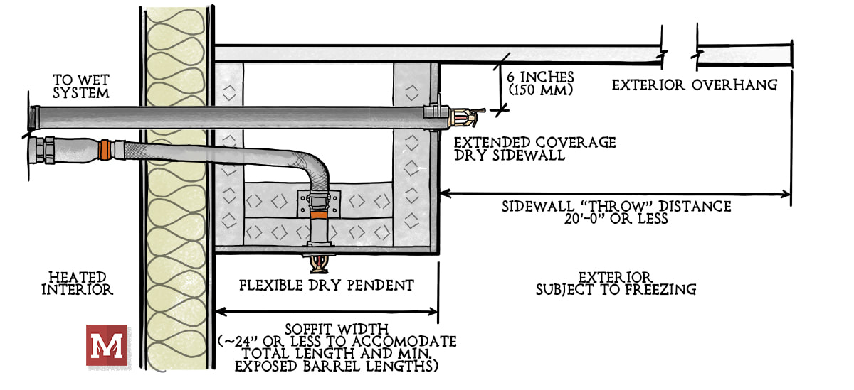 DIGGING DEEPER We also would want to offset these locations on plan, so a pendent isn’t immediately under a dry sidewall. Offsetting the locations in plan could help potential cold-soldering concerns. We’d also want to be sure that both the dry sidewall and the dry flex pendent would be able to be replaced at some point in the near future. NFPA 25 used to require sample testing or replacement every 10 years starting at 10 years after installation, but the 2020 edition bumped that starting point up to 15 years and the 2023 Edition bumped it again to 20 years after installation (NFPA 25 2017-20 Section 5.3.1.1.1.6, 2023 Section 5.3.1.1.1.5). To accommodate replacement and testing, we might need a way to get access to the inside and the soffit in the future (access panels or future cutout). COST & CONSEQUENCE After all this effort – will the soffit cost more? Sure. Would it cost as much as a dry or anti-freeze system? No, it shouldn’t. Does it help with corrosion and IT&M in the future, considering we wouldn’t have a dry valve and an additional nitrogen system or air compressor? Yes, that’d help too. Just an idea that might help address those “in-between” situations that could spike cost for a smaller-sized project that otherwise wouldn’t need it. What are your thoughts? Have you tried this before? What tips would you suggest? Hope you’ve found this interesting and perhaps moderately helpful, and I hope you have a great rest of your week! How do we solve the systematic problem we have with fire protection bid documents? Some, if not much of the plans and specifications that go out for bid are generally helpful. A quality set of fire protection bid documents:
These types of bid sets do happen. But far, far too often, they don’t. It’s systematic, and makes every step of the design and installation process far more difficult and far more costly than it could be. NOT FAULTLESS I don’t even want to pretend I’m not at fault here. I’ve designed poor projects. I’ve slacked on coordination, and detailing. I’ve glossed over parts of a project that I shouldn’t have glossed over. It’s been painful. But this is something that we can change. WHAT CONTRACTORS SAY For some years now I’ve spoken with sprinkler contractors, architects, and consultants about this. If you’re a contractor, especially if you work in estimating - you could provide countless examples of terrible bid documents. Bid documents that actually get in the way of you doing code-compliant, efficient work. You could speak to this far better than I can. In these conversations, over and over, I’ve heard one key feature that I think many consultants in the MEP space miss. It is far better to have no fire protection bid documents, than to have bad fire protection bid documents. NO FIRE PROTECTION BID DOCUMENTS? That’s important, and counterintuitive. It is far easier for a sprinkler contractor to look at a project and define their own scope, and put a price to it, than it is to try and bid a set of documents that:
If that sounds too far, ask your closest estimator friend. They see this all the time. How many projects do we see underground feeds piped 20-ft before rising up? How many times do we see Star, Central, or Gem still specified today, in 2024? How many times do we see projects wanting a fixed-price bid yet have zero information about the water supply? How are those documents helpful to a bidder? They’re not. MY ANALOGY The analogy that I’ve had in my head and finally am able to bring to life a little is the road, showing the different tiers of fire protection bid documents: 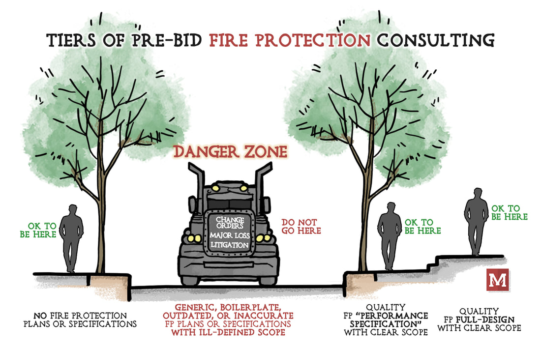 1 - NO FIRE PROTECTION BID DOCUMENTS
There’s the sidewalk on the left, where we have no fire protection bid documents. Let’s say we have a single-family home with an NFPA 13D system. Scope is simple, perhaps we have no specific owner needs, and it’s unambiguous. That type of project probably warrants no upfront, pre-bid fire protection involvement. It wouldn’t have to just be a single-family home though. What about an add & relocate job for a small retail space. Or a small office building. Those can, and often do, work just fine without any upfront fire protection bid documentation. Design-build all the way. 2 - QUALITY "PERFORMANCE SPECIFICATIONS" Then we skip ahead to quality “performance specification” documents. These do all the things we’ve talked about. They don’t necessarily show pipe or sprinklers, but they clearly define the scope, they communicate clearly, they answer major scope questions, they address and alleviate major issues or coordination challenges upfront, and they make it easy to put a price to the job. That’s a quality set of “performance specifications”. 3 - QUALITY "FULL-DESIGN" For high-end jobs, or high-hazard jobs, or critical function or high-visibility or unique jobs – perhaps we’re looking at a full-upfront design prior to bid. Full-design isn’t free, nor quick, and isn’t necessarily the answer for every job. But, as we’ve talked on this topic before; if it’s done well, and thoroughly, then fully-detailed plans can be a tremendous asset to a project. They can eliminate ambiguity and really dial-in exactly what work needs to be done. AND... THE DANGER ZONE What about the DANGER ZONE? There’s a gap, and it’s in-between no bid documents and quality “performance specifications”. And that is the Danger Zone. This is the lane of bad bid documents. These are all the bad things. Inconsistent, boilerplate, confusing, inaccurate, unachievable, irrelevant, or not actually code-compliant. What happens when we live in that lane? We get hit by the proverbial bus. Change orders. Litigation. Or much worse – a fire happens with major loss. This is not the spot to be. WHY DO WE STAY IN THE DANGER ZONE? I’m fairly confident that those who live in that space don’t want to be there either. They feel compelled because the client asks for fire to be included. They feel pressure because competitors are offering to do fire protection. They feel they can’t spend enough time on fire because there is hardly any fee there. Honestly – these are all poor excuses. If there isn’t enough money in the job to put together a quality set of fire protection bid documents – then don’t do them at all. It is far better to have no fire protection bid documents, than to have bad fire protection bid documents. HALF-BAKED DOESN'T HELP Bad, sloppy, half-baked documents don’t help. They don’t solve anything. They get in the way. If you’re the MEP who finds yourself in this area, having that conversation with an owner or architect and there’s just not enough fee to do quality work – then just exclude it entirely. If an architect insists that it get thrown in or done on a microscopic budget, then just ask them to hire a fire protection consultant separately. Half-baking a set of documents is not worth the hassle or the liability. It also doesn’t actually help. When you do take it on, do it well. We all benefit from that. YOUR TAKE If you’re a sprinkler contractor or architect – I really want to hear from you. Where do you land on this? When projects have gone south or had major change orders – what happened? Would being in a different tier have changed the result? Comment below, would love to hear your take. And, thanks, as always, for reading and being a part of the community here. We will get this right. USE GOOGLE FOR FLOW TESTS & SITE PLANS I sometimes (maybe often) have to learn things the hard way. This tip today comes from the “Lessons Learned” file, where it took me two bashings over the head before I had my ‘aha’ moment. Forgive me if this is obvious and you've been doing this for years. Again, I have to learn things the hard way sometimes. So what is it? What are we talking about? Clearly identifying the location of the water supply. And the ‘aha’ answer – well it’s really simple and can be really helpful. On many projects we use a flow test to get an idea of the available water supply. We use the available water supply curve to calculate how much pressure and how much flow we have available that can serve our suppression system (sprinkler, standpipe, etc). Flow tests carry a whole lot of engineering nuance. A flow test is simply an instantaneous “point in time”. It doesn’t account for demand variations like the time of day, day of the week, or seasonal demand like the lawn irrigation system next door. We’ll save that conversation for another day. One other key factor that a flow test carries is that it is highly dependent on the location from where the test was run. DOES THE LOCATION OF A FLOW TEST MATTER? If we have a large, looped supply, then the location horizontally may not play much of a difference. Say we have an Ordinary Hazard Group 2 sprinkler system and our main outside is a 12-inch looped main. The exact point which we tested isn’t going to affect our system all that much, because we wouldn’t get a lot of pressure loss in a 12-inch looped main when we’re only flowing 550 – 750 gpm. What if we’re not looped? What if it’s a dead-end 6-inch main instead of a looped 12-inch? Well, now our horizontal location could be critical. If our flow test is taken immediately adjacent to our building, then we have a high degree of confidence of what the water supply is doing right where we’re going to tap it. But, if our flow test was actually taken 1,500 ft upstream and we have a dead-end 6-inch supply, then we need to calculate the loss through that entire dead-end supply. That could be a lot of pressure loss! For example, for a 750 gpm sprinkler system, running friction loss for 1,500 ft of 6-inch pipe would lose 16.3 psi. That would have a major impact on most system designs. So, suffice to say, it can be important to document exactly where a flow test was taken horizontally. It also matters, however, in the other plane. DOES THE ELEVATION OF A FLOW TEST MATTER? There’s a chance, depending upon the project, that the horizontal location of a flow test may not play much of a factor in the system design. But the elevation of a flow test? That will always play a factor. If our static/residual hydrant (gauge hydrant in the diagram) is actually 30-ft lower in elevation than our project site, that has major implications. Let’s take a quick example. We look at results from a flow test showing a static pressure of 60 psi with a residual pressure of 50 psi at 1,200 gpm. If that test was taken at the same elevation as our project (a big large flat open field, for example), then we would expect a pressure gauge at the riser to be somewhere around 58-60 psi when nothing is flowing. The pressure gauge and the original gauge hydrant are very close in elevation. However, what if that test (those readings) was actually taken down the hill, at an elevation that was actually 30-ft lower than our project site? We would have a lot less available pressure. As we go deeper in a system, pressure increases. As we rise up within a system, pressure decreases. So a riser that is approximately 30-ft above the gauge hydrant would have an expected pressure of around 47 psi (60 psi – 30-ft x 0.433 psi/ft). That might not sound like much, but in some projects without a fire pump where we are already tight on the hydraulic calculations, this can be a major issue. AN EASY SOLUTION FOR THIS I’ve had two major project issues related to bad documentation of exactly where the flow test was taken. Most projects I see have a simple description for where a test was taken. It’s something like “at the corner of McKinley & Brower Streets” or “1000-ft east on Highway D from the flow hydrant”. Sometimes it’s a description like “on Highway T”. Having an intersection will generally help us narrow down which hydrant was actually used in the test. Usually. Having a description on the road doesn’t help us narrow down much, unless there’s only one hydrant within a half mile radius. What is very, very helpful for narrowing down which hydrant was used? GPS coordinates. USING GOOGLE MAPS Within google maps, it’s extremely easy to precisely locate any point on earth. You don’t even have to go into Google Earth, like we did in an article to grab elevation here. To grab any GPS coordinate on Google Maps, just right click and you’re presented at the top with the coordinates. Click on those coordinates to “copy” the coordinates where you can then paste them, as text, anywhere else.  Grabbing coordinates off Google Maps is as easy as right-clicking, then selecting the coordinates. Now, you can paste them into your flow test report, paste them onto your site plan, your hydraulic calculation report, or anywhere else. You only really need to go four decimal places for the coordinates – anything more and you’re talking about less than an inch – which of course is far too precise for what we need here.  Coordinates can then be pasted into anywhere - flow test reports, plans, hydraulic calculations. Anywhere you need. If later on, someone needs to verify a hydrant elevation, they can just copy and paste these same coordinates back into Google Earth (to get an elevation), or paste these right back into Google to get the location in Google Maps.  Later, anyone with those coordinates can paste them into Google or Google Earth (here), and find the location and the elevation at which those coordinates were taken. In Google Earth, the bottom-right corner shows the elevation. Using GPS coordinates for flow tests is extremely easy to do. What’s most important, though, is that by providing the coordinates for where the test was taken, you’re taking out so much ambiguity. Construction documents are only created for communication. If they don’t clearly communicate, then they’re not serving their purpose. I’ve only recently reached this ‘aha’ moment, but using the coordinates has already helped on recent projects. What about those two major project issues? What was up with those? One was related to a very poor description for where a flow test was taken (a flow test that I received from the city and failed to document well). The other was a flow test that had been taken a good 1,000 ft upstream on a 6-inch dead-end main. In either of these cases, had I correctly documented the exact location of the test, or had I received the exact location of the second test – we would have had no issues at all, because we could have accounted for these differences during the design of the project. Hope this tip helps you avoid some headaches in the future, and that you have a great rest of your week! - Joe Awhile back I wrote a piece on sprinklers in electrical rooms. At the time I was asked relatively frequently about when sprinklers are required or allowed to be omitted in electrical rooms. I guess intuitively, we recognize that electricity and water don’t mix well. We don’t want to address one problem (fire) by creating a new hazard (electrocution) with water in areas that it doesn’t have to be. In principle, I personally have just about always provided sprinklers in electrical rooms unless they were specifically requested not to be provided by the owner or AHJ; and in those cases, I followed the code path in the IBC or NFPA 13 accordingly. It seems as though the premise behind not including sprinklers is when the type of electrical equipment present a relatively low hazard or fuel source, and there is no storage. In that situation, a combination of 2-hour fire-resistance-rated enclosure with approved fire detection (assuming a smoke and/or heat detector here) will mean that a fire within the room will be recognized, and the rest of the building will not be compromised as a result. Providing pipe within an electrical room isn’t always an easy feat. NFPA 70 tells us that electrical equipment requires dedicated zones, and pipe shouldn’t be run above panels without drip pans or other methods of avoiding drip hazards above electrical equipment. 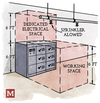 Now are sprinklers in electrical rooms problematic? Generally not (in my experience). Can pipe routing be made to avoid electrical equipment? Usually yes. I try to only run one branch line into the room, most often above the door (since no electrical equipment is on the door), and stick pipe only above walking pathways within the room. 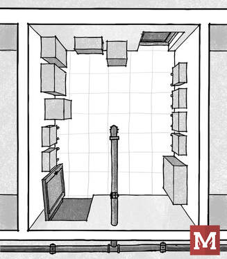 Does the code or standards express any concern or guidance on this? Yes, both the IBC and NFPA 13 address the situation. One line that is included in the IBC specifically says that sprinklers “shall not be omitted from any room merely because it...contains electrical equipment”. To me, that’s a fairly explicit way of suggesting that the presence of electrical equipment alone isn’t a justification for omitting sprinklers. Now there are code allowances and necessary provisions to do so, but the suggestion is not to simply avoid sprinklers just because there is electrical gear. Despite it being awhile since that article, I have had a few requests to make this one into a flowchart, which I’m happy to present today. A special thank you to Alex Riley, PE, who contributed to the code research for this flowchart. 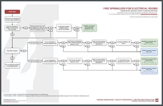
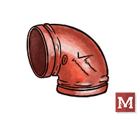
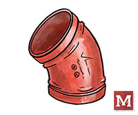
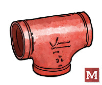
We previously have introduced different types and combinations of threaded fittings - which have been around for more than a century. Here we're introducing another common way to join pipe; using grooved fittings. 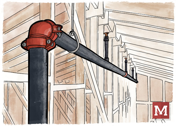 An attic sprinkler system using a grooved elbow with couplings. Use of "mechanical" couplings that could allow faster joining of pipe came to life in 1919 by Lieutenant Ernest Tribe. Just a few years later the Victory Pipe Joint Company renamed itself to Victaulic (a combination of "victory" and "hydraulic"), and grew to expand the technology worldwide. Today, Victaulic and other manufacturing leaders provide grooved fittings that are often used for pipes in fire sprinkler systems. It is not uncommon for both mains and branch lines to be grooved today. What are common grooved fittings, and how do they work? Let's introduce them. 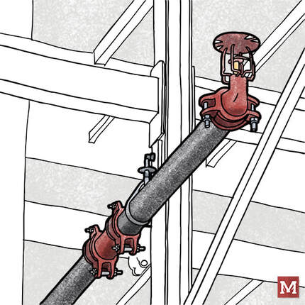 An in-rack sprinkler with a branch line using (starting with the sprinkler) a groove x thread reducing elbow with a grooved coupling, a grooved piece of pipe, and a grooved tee (connection not shown). PIPE Let's start with the pipe. In order to give grooved fittings an opportunity to "grip" the pipe and remain in place, they need an opportunity to resist the pressure of the water that is trying to "pull away" the pipe from the fittings which join them together. 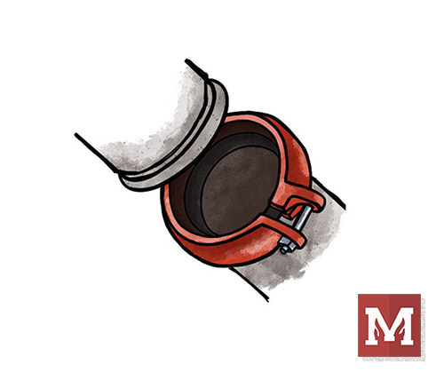 A grooved coupling about to connect two grooved-end pipes. Note the loose nut and bolt on the right-hand side, allowing the coupling to be expanded and "slip" over the pipe on the left. In order to create a groove in the pipe, steel can either be "roll groove" or "cut groove". Roll groove pipe involves pressing an indentation into the pipe near the end of the pipe. This allows a grooved fitting to slip over the end of the pipe and fit into the groove. Roll groove pipe has the advantage of not reducing the pipe thickness, so it can have more tolerance for corrosion than thinner pipe, similar pipe with threads, or pipe with cut grooves. Pipe which is cut groove involves cutting into the pipe rather than pressing it. This cutting removes a portion of the pipe wall, making a thinner but smooth interior pipe wall. This thinner wall makes it more susceptible to corrosion, however, for pipe systems with a minor slope, the smooth inside of the pipe does not create a ridge where water can sit and corrode the pipe. 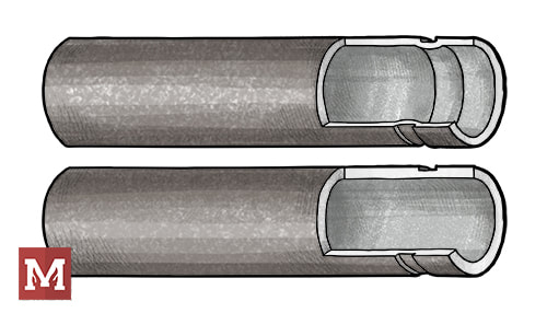 Roll Grooved Pipe (top) and Cut Grooved Pipe (bottom). Note the ridge on the inside of the pipe wall for roll groove pipe, and the thinner pipe wall along the cut groove pipe.  A tape measure with a "go" or "no-go" measurement to determine if the groove is within manufacturer tolerances. ELBOWS & TEES Let's start with the basics. Elbows allow bends of 90-degrees (most common), 45-degrees, 22-1/2 degrees, and 11-1/4 degrees. Why not every possible angle? What if I need to have a 60-degree bend because of my building? First, it wouldn't be economical to make a fitting of every bend. Second, is that using just two 90-degree elbows back-to-back we're able to create a "swing joint" and make any angle we could want, just by changing the elevation of the pipe that's being joined.
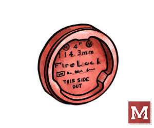
Victaulic "FireLock" Grooved Fittings; 90-Degree Elbow #001 (left), 45-Degree Elbow #003 (center), and Standard Tee #002 (right) One notable specialty with the grooved elbow is a "Drain Elbow", which has the elbow except it includes a drain outlet at the bend of the elbow. This is used all the time with fire department connections which come down a wall and need to be capable of being drained (to avoid having water-charged pipe freeze and burst). This is also called a "Drain-El" or is a Victaulic #10-DR. 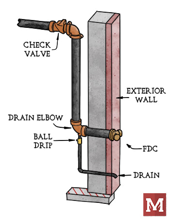 A wall-mounted fire department connection that is away from the riser, here showing the "Drain Elbow" with a ball drip below. The portion upstream of the check valve is intended to be dry unless the FDC is actively being used in order to avoid freezing water inside. COUPLINGS Nice sketches, Joe, but that's not how things look in the field! That's because unlike threaded fittings, the actual pipe joining is by a grooved coupling. The coupling has malleable iron bumps that grip the indent of one groove (pipe/fitting) and connect it to the second groove (the other pipe/fitting). 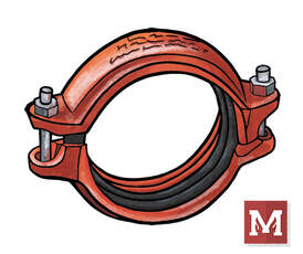 A grooved coupling (here a Victaulic #009N shown). OTHER FITTINGS There are a host of other fitting types. Grooved Reducing Tees? Yep. Less common. Less common can equate to more expensive, or at least that's what I hear from contractors familiar with all the pricing nuances. What other grooved fittings do I often see? Reducing fittings, which is a concentric, single-cast piece of metal that has a large groove on one end and tapers down to a smaller groove on another end. One note of caution is using these in the vertical orientation; I've heard it is much better, more stable, and stronger to use a reducing-fitting as opposed to a reducing-coupling when in a vertical orientation. One of my clients goes so far to say to not use reducing couplings at all (where the coupling itself has two different groove sizes). I wouldn't have the expertise to gauge that myself.
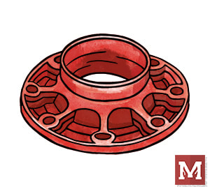
A flange x groove reducer (left) and a grooved cap (right). There are also reducing adapters, than can accept a flange connection and convert it to a reduced groove connection. Crosses are also available, as are caps (like the Victaulic #006 shown above on the right) which can terminate the end of a branch line. These caps even have 1-inch threaded opening options for easy auxiliary drains.  Many manufacturers have equipment and components with grooved ends that can readily attach to pipe and fittings. If you're looking to explore the extend of all available grooved fittings, I'd invite you to check out manufacturer's catalogs or do a simple google search for grooved sprinkler pipe fittings. The manufacturer's product data can do a whole lot of good in clarifying what's been created and listed for use in sprinkler systems. Have tips, tricks, or things to consider about grooved fittings? Comment below. That's all for this week - hope you have a great rest of yours. This week I'm happy to debut an update to one of our popular tools, the K-Factor selector, which is a part of the Toolkit. This tool quickly calculates the actual pressure and flow across different types of sprinklers. It's helpful when we're trying to select the best-possible sprinkler for a hazard. Even for light hazard areas, a standard k5.6 sprinkler may not be the 'optimal' sprinkler, from a hydraulic perspective. We touched on this when looking at whether the flow through a sprinkler is governed by the density and area or by the k-factor and minimum pressure. In short, the minimum flow through a sprinkler can be driven by the coverage area of the sprinkler multiplied by the density of the hazard, or, it can be driven by the k-factor of the sprinkler and the minimum pressure that sprinkler requires.  In either case, it's important to make a quality selection for the k-factor if we want to reduce the required pressure and flow that a system will demand. Less flow usually means less friction loss, which can result in more efficient systems and smaller pipe sizes (saved cost of material and labor).
The updates to this tool make it mobile and tablet friendly, and also now clearly indicate what the 'optimal' sprinkler k-factor is for flow and for pressure (hint: they're not always the same). If you're a Toolkit user, just click the image above to see the updates. Thanks! |

ALL-ACCESS
SUBSCRIBEGet Free Articles via Email:
+ Get calculators, tools, resources and articles
+ Get our PDF Flowchart for Canopy & Overhang Requirements instantly 
+ No spam
+ Unsubscribe anytime AUTHORJoe Meyer, PE, is a Fire Protection Engineer out of St. Louis, Missouri who writes & develops resources for Fire Protection Professionals. See bio here: About FILTERS
All
ARCHIVES
July 2024
|
 RSS Feed