
|
We previously have introduced different types and combinations of threaded fittings - which have been around for more than a century. Here we're introducing another common way to join pipe; using grooved fittings. 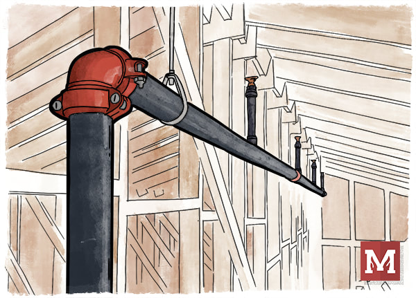 An attic sprinkler system using a grooved elbow with couplings. Use of "mechanical" couplings that could allow faster joining of pipe came to life in 1919 by Lieutenant Ernest Tribe. Just a few years later the Victory Pipe Joint Company renamed itself to Victaulic (a combination of "victory" and "hydraulic"), and grew to expand the technology worldwide. Today, Victaulic and other manufacturing leaders provide grooved fittings that are often used for pipes in fire sprinkler systems. It is not uncommon for both mains and branch lines to be grooved today. What are common grooved fittings, and how do they work? Let's introduce them. 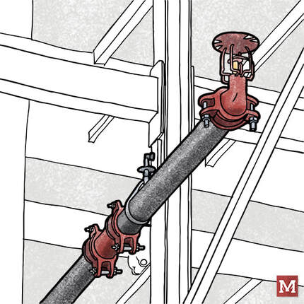 An in-rack sprinkler with a branch line using (starting with the sprinkler) a groove x thread reducing elbow with a grooved coupling, a grooved piece of pipe, and a grooved tee (connection not shown). PIPE Let's start with the pipe. In order to give grooved fittings an opportunity to "grip" the pipe and remain in place, they need an opportunity to resist the pressure of the water that is trying to "pull away" the pipe from the fittings which join them together.  A grooved coupling about to connect two grooved-end pipes. Note the loose nut and bolt on the right-hand side, allowing the coupling to be expanded and "slip" over the pipe on the left. In order to create a groove in the pipe, steel can either be "roll groove" or "cut groove". Roll groove pipe involves pressing an indentation into the pipe near the end of the pipe. This allows a grooved fitting to slip over the end of the pipe and fit into the groove. Roll groove pipe has the advantage of not reducing the pipe thickness, so it can have more tolerance for corrosion than thinner pipe, similar pipe with threads, or pipe with cut grooves. Pipe which is cut groove involves cutting into the pipe rather than pressing it. This cutting removes a portion of the pipe wall, making a thinner but smooth interior pipe wall. This thinner wall makes it more susceptible to corrosion, however, for pipe systems with a minor slope, the smooth inside of the pipe does not create a ridge where water can sit and corrode the pipe. 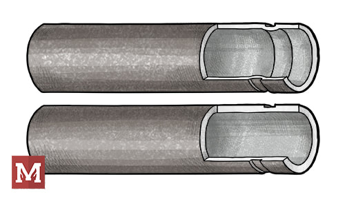 Roll Grooved Pipe (top) and Cut Grooved Pipe (bottom). Note the ridge on the inside of the pipe wall for roll groove pipe, and the thinner pipe wall along the cut groove pipe.  A tape measure with a "go" or "no-go" measurement to determine if the groove is within manufacturer tolerances. ELBOWS & TEES Let's start with the basics. Elbows allow bends of 90-degrees (most common), 45-degrees, 22-1/2 degrees, and 11-1/4 degrees. Why not every possible angle? What if I need to have a 60-degree bend because of my building? First, it wouldn't be economical to make a fitting of every bend. Second, is that using just two 90-degree elbows back-to-back we're able to create a "swing joint" and make any angle we could want, just by changing the elevation of the pipe that's being joined.
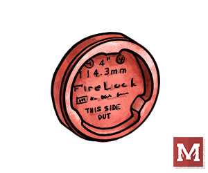
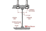
Victaulic "FireLock" Grooved Fittings; 90-Degree Elbow #001 (left), 45-Degree Elbow #003 (center), and Standard Tee #002 (right) One notable specialty with the grooved elbow is a "Drain Elbow", which has the elbow except it includes a drain outlet at the bend of the elbow. This is used all the time with fire department connections which come down a wall and need to be capable of being drained (to avoid having water-charged pipe freeze and burst). This is also called a "Drain-El" or is a Victaulic #10-DR. 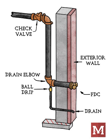 A wall-mounted fire department connection that is away from the riser, here showing the "Drain Elbow" with a ball drip below. The portion upstream of the check valve is intended to be dry unless the FDC is actively being used in order to avoid freezing water inside. COUPLINGS Nice sketches, Joe, but that's not how things look in the field! That's because unlike threaded fittings, the actual pipe joining is by a grooved coupling. The coupling has malleable iron bumps that grip the indent of one groove (pipe/fitting) and connect it to the second groove (the other pipe/fitting). 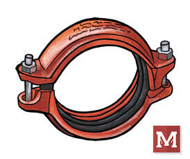 A grooved coupling (here a Victaulic #009N shown). OTHER FITTINGS There are a host of other fitting types. Grooved Reducing Tees? Yep. Less common. Less common can equate to more expensive, or at least that's what I hear from contractors familiar with all the pricing nuances. What other grooved fittings do I often see? Reducing fittings, which is a concentric, single-cast piece of metal that has a large groove on one end and tapers down to a smaller groove on another end. One note of caution is using these in the vertical orientation; I've heard it is much better, more stable, and stronger to use a reducing-fitting as opposed to a reducing-coupling when in a vertical orientation. One of my clients goes so far to say to not use reducing couplings at all (where the coupling itself has two different groove sizes). I wouldn't have the expertise to gauge that myself.
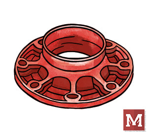
A flange x groove reducer (left) and a grooved cap (right). There are also reducing adapters, than can accept a flange connection and convert it to a reduced groove connection. Crosses are also available, as are caps (like the Victaulic #006 shown above on the right) which can terminate the end of a branch line. These caps even have 1-inch threaded opening options for easy auxiliary drains. 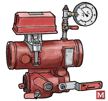 Many manufacturers have equipment and components with grooved ends that can readily attach to pipe and fittings. If you're looking to explore the extend of all available grooved fittings, I'd invite you to check out manufacturer's catalogs or do a simple google search for grooved sprinkler pipe fittings. The manufacturer's product data can do a whole lot of good in clarifying what's been created and listed for use in sprinkler systems. Have tips, tricks, or things to consider about grooved fittings? Comment below. That's all for this week - hope you have a great rest of yours. Drainage from a fire sprinkler system can often be overlooked as it does not directly fight the fire. However, those involved in inspections & testing of sprinkler systems know all too much about how poor drain design for a sprinkler system can negatively impact how tests are conducted, how long it takes a system to drain, and what messes building owners have to deal with. Here are various components for drains on a sprinkler system, and some of the common requirements that pair with them. 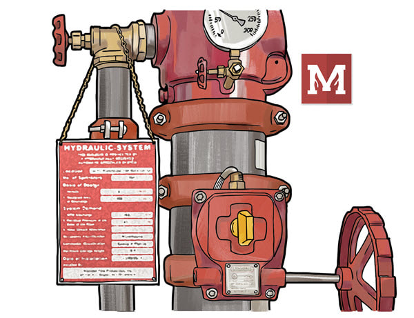 For best viewing of the table below, click here: requirements-for-drains-in-fire-sprinkler-systems.html
Design-specifications have had a tradition and sometimes contemptuous past in the world of fire protection design. Sometimes called “design-build spec”, “performance-specification”, “delegated design”, “deferred submittal documents”, “scope drawings”, or “design-spec”, these all mean relatively the same thing; the engineer is not providing a working submittal of how a fire suppression system should end up in the field. Back in 2008 advocacy groups from the Society of Fire Protection Engineers (SFPE), National Society of Professional Engineers (NSPE), and National Institute for Certification of Engineering Technologies (NICET) adopted a joint position on the role of the Engineer and the Engineering Technician as they relate to fire protection systems. A summary and full-length document are here. The position statement does a good job of identifying the relationship between engineering documents and a working shop drawing submittal. It maintains that the role of the Engineer is to support the proper protection of the public’s health and safety. A licensed Engineer is required to understand a broad sense of fire protection beyond just suppression, and also has specific state requirements for licensing and authorization. While the position statement does a good job of identifying roles and defining the relationship between an engineer and a technician, real-world experience says that many “design-build specifications” fall short on good practice. I’ll save my frustrations on the lack of quality engineering documents for another day (it is not a regional issue). There is a ton to explore on that topic. I will however offer up what I like to use as a practical checklist for design-build specifications. Not all owners want to pay consultants to flush out all the details of a system. I get it. But if an owner is paying for anything at all, then the documents should address basic requirements and cost-impacting elements of design. 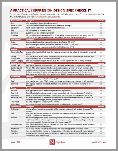 If a set of plans just outlines an area and says “per NFPA 13”, then someone isn’t doing it right.
This cheatsheet is a collection of the items I’m looking for when I help contractors bid jobs. It’s a shortcut to all of the items that have a design and cost-impact to a job. If you, as a consulting engineer, address every single one of these items clearly and within code, then pat yourself on the back my friend, you are a gift. If your documents don’t address each of these items (yes, including flow test information), consider making it a part of your regular practice. None of the items on this list are major time consumers, but by accounting for them you’ll allow better bidding from contractors and much less contention after bids are due. Please, please: don’t loft up vague project requirements to contractors and hope for the best. Invest in being a knowledgeable and quality practitioner of this great industry. It'll more than pay itself back to you. What are your thoughts? What type of bid documents are you used to seeing? Join the conversation and comment here. This time of year is just the best. I feel extremely fortunate to have three young kiddos at home, a supportive and all-around great family, and an extremely rewarding career in fire protection and doing what I do here at MeyerFire.com. Whether you subscribe, dabble occasionally on the forum, or just stop in to use tools here and there, THANK YOU for a really wonderful 2019. One of the tasks of wrapping up a year is revisiting what resonated the most in 2019 of all the content here. If you just joined in this year or know someone who would benefit from this content, please consider sending a link.
While we're at it, here are the Top Ten Tools & Articles of 2018 and the Top Ten Tools & Articles of 2017. Hope you have a relaxing and rewarding holiday week wherever you call home! This week I'm pulling back the curtain a little bit and showing a tool that is very much still under development. It's a water-storage tank sizer that incorporates a handful of decisions that go into water storage tank sizing. I'd like to get it in front of you this week as I'm looking for feedback on how to improve this tool. There's not a lot of great documentation on how to size water storage tanks, but there are plenty of variables that impact proper water storage tank sizing. With that said, check out the tool as part of our Toolkit package here: If you're in the water storage tank space and have tips or feedback, please email me at [email protected] or comment here. I'd be very much interested in ways to improve this one (or any tool for that matter). On a side note, this and many other recent tools are going to be included with a major MeyerFire Toolkit update here in the next few weeks. We've been working quite a bit on improving the activation/subscription process which has been no small task. When that gets cleaned up I'll be happy to send out the major update for the Toolkit. Hope you have a great rest of your week!
I was asked recently for a specific project how much flow the owner should anticipate coming from a building's main drain.
There's just a few factors that play into exactly how much water to expect. Is the drain serving as the main drain for a system? Is it only serving an inspector's test? Is the drain off a 1-inch pipe, or 2-inch? How much pressure is on the system? These aren't often difficult to answer if you're familiar with the job, but each of these answers plays a role in determining how much water will come out of an open orifice. This week I've simplified a few of these parameters to come up with a quick inspector's test and drain calculator for fire sprinkler systems. With it, you can estimate the amount of flow that will come from an inspector's test (use the k-factor option) or from a drain (diameter option). For our international audience I have incorporated real units from the get-go this time. It's a free tool that's now live on the site, here. Give it a spin and let me know what you think in the comments here. Know others that might find this helpful? Send them a link or tell them to subscribe here. Thanks & have a great week! There’s no real way around it: I love cheatsheets. In a design course in college we received 5x7 index cards to include any handwritten notes we wanted for an upcoming final. I wrote so much on that card with handwriting that was effectively size-4 font that it could have been displayed as a work of art. Nearly an entire semester summarized to a 5x7 card. It was a thing of beauty. While I no longer have a need to write so small, I still enjoy having information organized so that it is extremely easy to access. If you haven’t seen these before, here are a couple cheatsheets I’ve created so far: Summary of Differences of NFPA 13, 13R, and 13D Sprinklers & Passive Fire Protection Options
Last week I covered important considerations surrounding fire department connections from a design perspective, which was a joint-effort with QRFS covering the topic. At some point I’ll compile the best blog posts and resources into a hardcover reference book. For this week, however, here’s a cheatsheet on requirements surrounding fire department connections across NFPA 13R, NFPA 13, and NFPA 14:
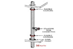
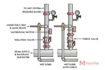
Why are fire department connections (FDCs) so important to a suppression system? They are the link between initial response and supplemental help. Despite appearances, sprinkler systems are not intended to discharge forever. Their goal is to suppress long-enough that firefighters can take over and finish the job. Standpipe systems exist to extend the reach of the fire department in tall, wide or complex buildings. Manual standpipes depend upon pressure and flow from the fire department. What single piece of equipment is relied upon to make the transfer? The FDC. This week's article is an overview of fire department connections from an engineer’s perspective. It is one part of a two-part series covering fire department connections. Read more from a supplier’s perspective at Quick Response Fire Supply here. Authority Intervention Needed Fire department connections are a unique piece of a suppression system in that they’re not just governed by the designer and code. NFPA 13 and 14 require that fire department connection type and location is coordinated with the Authority Having Jurisdiction. Early in design, prior to bid, I’ll call the local fire marshal and coordinate each of the following big-picture elements: Coordination Item 1: Type of Fire Department Connection The most popular types of FDCs? Siamese (2 x 2-1/2" threaded connection) and Storz (4" or 5" with or without 30-degree elbow). In my very unscientific study of jurisdictions I call (nearly half are local to my area), I've found the following; 73% use Siamese-type 2-1/2” fire department connections, 11% use 4” Storz connections, and the remaining 16% use 5” Storz connections. Of these, 13% have special requirements such as Knox Locking caps, 30-degree elbows, or irregular threading. There’s no right or wrong answer here – I just want to be sure what I’m calling for or showing on plans match what the jurisdiction uses. 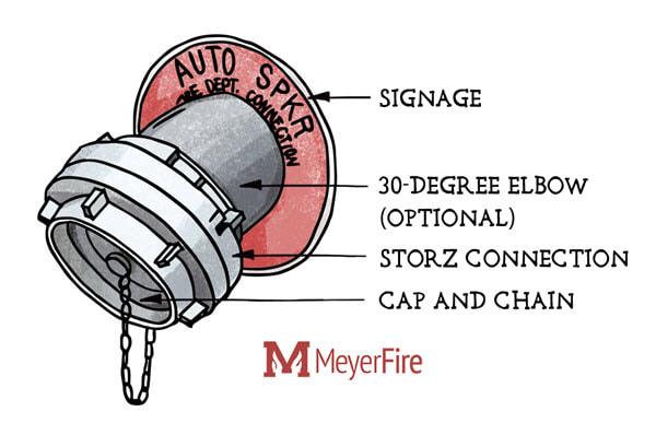 Large diameter Storz-type fire department connections have become more common for their ability to quick-connect a single hose and flow large amounts of water. Coordination Item 2: Location of Fire Department Connection The most obvious coordination during design is the location of the fire department connection. My design preference, driven by installation effort and cost, is typically in the following order: 1. Wall-mounted FDC, adjacent to the sprinkler riser 2. Wall-mounted FDC, remote from the riser (such as the front of the building) 3. Freestanding FDC, downstream of a site backflow pit or hotbox 4. Freestanding FDC, connected underground into the sprinkler riser room The first couple options are not always workable and depend on the building. Sometimes the water supply and riser room are in the back of a building inaccessible to the fire department. This would be a bad place for an FDC. Sometimes the front face of a building is "grand view" with large glazed curtain walls and no room to mount a fire department connection. This comes up with large offices or modern schools. Sometimes a building-mounted FDC doesn’t make sense with major hazards; why risk firefighter safety in these cases? High-rises, for instance, require multiple FDCs due to the potential for falling glass that could injure firefighters or sever hoses. If there's potential for wall-collapse (think high-hazard warehouse wall) then a wall-mounted FDC also may not make sense. Freestanding FDCs can make a lot of sense for projects like these. Considering most of my work is two stories or less and light commercial, it may not be surprising that roughly 85% of projects include building-mounted FDCs. The remaining 15% have necessitated freestanding FDCs. 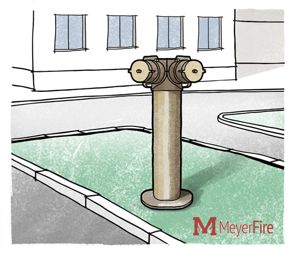 Some jurisdictions require freestanding fire department connections, but it typically depends on the type of building and hazard presented. Coordination Item 3: Distance of FDC to Nearest Hydrant As a designer it would be great if I could operate in the dark. Send me all the information I need to do a design, I do it, and everyone’s happy. If it were that simple, though, we’d probably already have machines design and do it without downing two bags of Doritos and a half hour of facebook each day. Back to the topic: FDC-to-hydrant distance has an impact on the tactical approach in firefighting. Many designers & installers in our field are current or former firefighters. They could readily speak to this. I’m not one of them, but I can imagine that having to shut down a major roadway or cross a parking lot with hundreds of feet of hose quickly during an emergency is not exactly the easiest thing to accomplish. As a result I like to ask AHJs what distance the FDC should be to the nearest hydrant. Of my highly unscientific and locally-biases results, 41% of jurisdictions require a hydrant to be within 100 feet of the FDC or less, 47% require a hydrant to be within 150 feet, and only 16% of jurisdictions require a hydrant within 200 feet or more of the FDC. These three elements are a part of my code calls. Next week I'll distribute my FDC Cheatsheet that outlines requirements for FDCs across NFPA 13, 13R and NFPA 14. If you haven't already subscribed, consider doing so here. What do you look to coordinate with the AHJ? Discuss your experience here. Want more coverage on fire department connections? See the other half of our two-part series on fire department connections here: Quick Response Fire Supply. One project question I very commonly receive from civil engineers is whether a post-indicator valve (PIV) is required. In short, there are options. I'm exploring PIVs in more detail in this week's article. If you want to get more like this, subscribe for free here. Purpose of Post-Indicator Valves Post-indicator valves have long been used to stop the flow of water into a building during developed stages of a fire. Exterior wall collapse of a burning building poses a threat to break water supply mains as well as create many openings to the water supply. Without a valve to stop supply to these areas, firefighters and their efforts could be compromised by the loss of pressure and outflow of water to areas of a site that don't need water. With the recognized effectiveness of sprinkler systems and cost pressures, the requirement for post-indicating valves have become more relaxed in the last decade. Code references to account for building collapse, for instance, now appear only indirectly in location requirements for hydrants and post-indicator valves to be sufficiently away from a building. Components of Post-Indicator Valves The post-indicator valve has several important features - first is the ability to quickly shut the valve with use of the post indicator valve handle. The second is to quickly see whether the system is in the 'open' or 'shut' condition in a protected enclosure. It can sometimes be difficult to see after years of dirt on the glass, but not impossible. The valve itself is along the water main below frost depth such that only the stem is subject to freezing conditions. It's a simple concept that's carefully crafted to protect the valve and stem in a reliable fashion. 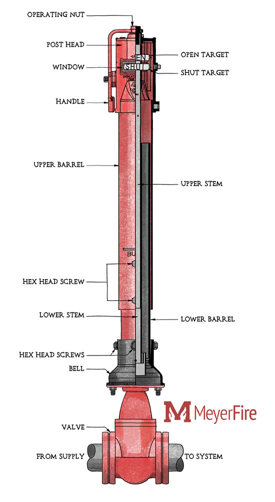 One example of a post-indicating valve - a Mueller Company Vertical Adjustable Post Indicator Valve (see https://www.muellercompany.com/fire-protection/ulfm-indicator-posts/) History of the PIV Requirement So is a post-indicator valve required or not? This used to be an easier question to answer. While not a referenced standard from the International Building Code, the International Fire Code requires that all private fire service mains be installed in accordance with NFPA 24 (IFC 2000-06 Section 508.2.1, 2009-18 507.2.1). NFPA 24, the Standard for the Installation of Private Fire Service Mains and Their Appurtenances, governs system requirements between a water supply main and a building's service entry. Up until the 2010 Edition, NFPA 24 required a listed post indicator valve on every connection from a private fire service main to a building unless special criteria were met (NFPA 24 Section 6.3). The special criteria included the use of a non-indicating underground gate valve with a roadway box and T-wrench or locating an inciating valve in a pit. Either special case required approval of the AHJ. Current Valve Options within NFPA 24 Since the 2010 Edition, NFPA 24 gives a series of options for isolating a building's system and does not mandate that a post-indicator valve be used. These options (from 2010-13 6.2.11, 2016-19 6.2.9) include:
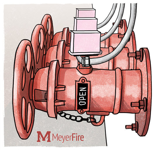 While still considered an "indicating" type valve, wall indicating valves are generally less preferred than post-indicating valves as they are more susceptible to a building collapse than post-indicating valves. Post-Indicator Requirements of NFPA 14 NFPA 14, the Standard for the Installation of Standpipe and Hose Systems, also weighs in on post-indicator valve requirements. NFPA 14 requires that each water supply (except for an FDC) shall be provided with a listed indicating valve in an approved location (NFPA 14 2000 4-2.6.1, 2003-07 6.2.6.1, 2010-19 6.3.6.1.1). The prescriptive way to accomplish this is through the use of a post-indicating valve. Annex material within NFPA 14 goes further, stating a list of preferences for outside control valves:
NFPA 14 does give exceptions (as is almost always the case in fire protection), but they require AHJ-approval. Wall-point-indicating valves, or underground valve with roadway box and T-wrench, are alternative options that require AHJ approval (NFPA 14 2000 4-2.6, 2003-07 6.2.6, 2010-19 6.3.6). Post-Indicator Requirements of NFPA 13 So where does NPFA 13 stand on post-indicator valves? In short, it doesn't. NFPA 13 only states that where post-indicator valves are used, the top of the post must be 32-40 inches above grade, and they must be protected against mechanical damage (NFPA 13 2002 8.15.1.3, 2007-16 8.16.1.3, 2019 16.9.9). AHJ & Insurer Inputs Authorities Having Jurisdiction may also want to weigh in on requirements for post-indicating valves. Some municipalities write code amendments to require PIVs, while others may request PIVs be installed for certain building types. Insurers, such as FM Global, may also want input. FM Global for instance, recommends that each system has a control valve a minimum of 40 feet from the building (with less preferred options also recommended in Data Sheet 2-0 2.6.2). Best Practice What's the best course of action for your project? First, check for local or state code amendments that may affect post-indicating valves. If you have a standpipe system within the building, plan to provide a PIV. Last, check with your AHJ for any nuanced requirements you may be missing or to coordinate a location with the AHJ. Want More? Not already getting these free weekly articles? Subscribe here. Found this helpful? Share on LinkedIn.com or send to a friend. MeyerFire is all about helping you do great work in fire protection with tools, tips and resources. I'll start by saying I'm not perfect. I've learned some things the hard way that I could have avoided, which in part spurned this whole blog. This week's topic covers one of those things learned by trial and error (but mostly error). If you are responsible for fire protection bid plans and you expect a contractor to provide hydraulic calculations, then you should include flow test information on your plans. "If you are responsible for fire protection bid plans and you expect a contractor to provide hydraulic calculations, then your plans should include flow test information." NFPA 13 does just about everything but require a flow test to be completed on the preliminary plans. Annex material, for instance, has long spelled out that preliminary plans should be submitted to the AHJ prior to the development of working plans by a contractor (A.14.1 in 2002 Edition, A.22.1 in 2007-10, A.23.1 in 2013-16, A.27.1 in 2019). These preliminary plans should include test information with date and time, conducting party, location of hydrants, and size of mains. 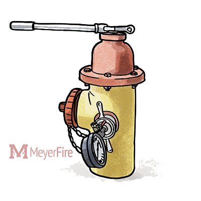 Water supply information is a critical part of the overall fire protection equation but it's value comes before bidding as well as after. If it is not a requirement in 13 to have it included in preliminary plans, then why provide it when the contractor can? Well, there are several reasons. 1. Determine Fire Pump & Water Storage Tank Prior to Bidding Is a fire pump required for the project? It’s an important question – the cost impact to an owner is often between $50,000 and $120,000 between the pump, controls, piping and equipment, and possible generator when a pump is required. 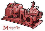 The only thing more expensive than a fire pump or water storage tank included on a project is when they get added as a change order. Is the available flow to the site low, needing a break-tank or a full water storage tank? The cost impact to an owner here is even greater. If a flow test is not included on preliminary plans, how is a contractor supposed to confirm that a pump or a tank are not necessary? Take the word of the engineer? Guess based on past-history? For flat-terrain areas with little construction activity over time, anticipating the available supply might be possible. For hilly areas where I live with a wide variety of water main sizes, it can be next-to-impossible to guess an available water supply at any given location. If you are a prudent contractor and you are to bid a job without clear water supply information, what would you do? Bid a price conservatively high to anticipate large pipe sizes with a poor water supply? That’s possible – but then you’re also far less likely to win the job. Bid a competitive price, but exclude larger pipe sizes or a fire pump/tank? That could work to win the job, but what happens when the actual flow test is run and you determine a fire pump is necessary? I’ll tell you what happens – the owner gets a very large change order they weren’t anticipating and the general contractor, sprinkler contractor, and design team all look bad. Part of my role is creating upfront preliminary plans for owners & architects that go out to bid, but I also work for sprinkler contractors to produce installation/shop drawings. I’m very fortunate in that I get to see both sides of the industry. A Real-World Example One current job that I’m working for a local sprinkler contractor on is a new-construction five-story medical office building. It’s a great building with tall floor-to-ceiling heights and a fifth-story ceiling that’s about 80 feet above ground level. The preliminary plans call for an FM Global Hazard Category-2 shelled area (0.20 gpm over 2,500 sqft) on the top level. Once the flow test came in, even with good pressure, it wasn’t enough to support this hazard classification. Could the hazard classification get bumped down to better align with the future tenant use? Possibly. Could a fire pump be added to the project at a significant cost, late in construction? Possibly. Either case, this all could have been avoided had flow test information been provided on the original plans. Bidding contractors wouldn’t be eligible to claim large change orders based on unanticipated pressure, and they can flag issues before they even submit bids. 2. Reduce Potential for Major Change Orders Too often the single cost that a building owner is concerned with is the total cost of the job at bid. They should be concerned about the total cost of the project, including change orders and including the lifecycle of the system. What good does accepting a low bid do if it is later rife with change order cost additions? It happens all the time with poorly prepared bid plans. Including a flow test as part of the preliminary plans removes a major potential change order opportunity as it enables the sprinkler contractor to do their own pre-bid layout and calculation should they choose to do so. 3. Removes Potential Conflict of Interest I have encountered misreadings of pressures from a gauge in the field, test results that were incorrectly copied between documents, and flow tests that were suspicious enough to go and re-test. I (thankfully) have never come across anyone doctoring flow test numbers. Is it possible that a contractor could fudge flow test numbers to save on pipe sizes and improve their bottom line? It’s possible. Virtually all of the contractors I’ve come across are very proud of their installations and are in the business because they care about life safety. Have I ever seen it happen? No. Could it? Yes. When an engineer provides the water supply information upfront, however, this potential conflict of interest evaporates. 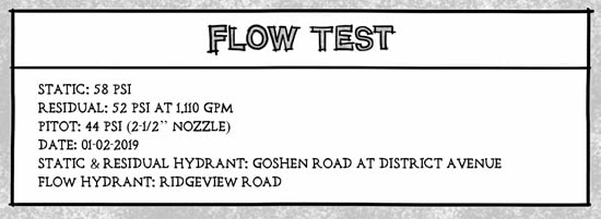 Including flow test data (or fire pump/water storage tank information) can be a critical piece for bidders to properly assess and bid a system. 4. It’s Not That Hard to Get For all the information we expect contractors to produce after they win a job, could we as engineers not produce such an important (and basic) piece of information? Some water purveyors run hydrant flow tests at no cost. Some jurisdictions will do the same. Even when both don’t run the tests, you can do it yourself. Read and follow NFPA 291, watch some videos, pickup a flow test kit for $400-$600, and remember to open and close valves slowly. It’s not terribly hard to do. If you aren’t interested in running the test, hire a contractor. I’ve seen tests run as cheap as $150 and as expensive as $1,200 (a 3-hour drive each way), but they are often between $350 and $550 to have completed. Local contractors are more than capable of providing this service and they can do so quickly. One of the biggest hassles in running a test early is often the tight design schedule many projects are on, and explaining to the owner why a flow test should be done upfront when a sprinkler contractor could just to it later. This article at least helps you address the later concern. 5. It’s Fair to Bidders Bidding contractors are often not as concerned about how much or how little you want them to do. If you want schedule 40 throughout, they’ll provide schedule 40 throughout. If you want a nitrogen system, they’re provide a nitrogen system. What contractors are extremely concerned about is that their bid price is fairly compared to other contractors. They will not provide schedule 40 if they feel another contractor will not provide it. Same with nitrogen or any other upgrades that could otherwise greatly benefit the building owner. Water supply information is one of those key pieces of information that allow contractors to bid on an even playing field. 6. Retain Data History How often do you find old building design documents that don’t include shop drawings? If you’re like me, it’s all the time. An engineer’s pre-bid plans don’t often have a wealth of helpful information – but having a little water supply block is a helpful data point when comparing historical water supply points. Since engineer’s preliminary plans often get stored and tracked with the rest of the construction documents, including the water supply information can be a helpful way to retain that information for designs and renovations in the future. I’ll slowly now descend from my soapbox by saying again that I’m not perfect. I’ve sent far too projects out to bid without water supply information than I would like to admit, often without any legitimate excuse. As an in-house goal we now try to hunt down water supply information for every project that we expect to see a hydraulic calculation by the contractor. That’s every building addition, occupancy hazard change, and every new construction project. It’s just too important of a data point to leave out for bidders.
Enjoy articles like this? Subscribe here. Already subscribed? Send to a colleague or friend. |

ALL-ACCESS
SUBSCRIBEGet Free Articles via Email:
+ Get calculators, tools, resources and articles
+ Get our PDF Flowchart for Canopy & Overhang Requirements instantly 
+ No spam
+ Unsubscribe anytime AUTHORJoe Meyer, PE, is a Fire Protection Engineer out of St. Louis, Missouri who writes & develops resources for Fire Protection Professionals. See bio here: About FILTERS
All
ARCHIVES
July 2024
|


 RSS Feed