
|
A quick update this week - back in 2018 I put together a flowchart for when sprinklers are required in closets. It was nice and had some nice feedback, but it only pertained to the 2016 Editions of NFPA 13, 13D, and 13R. This week I went back and made some major updates for references from the 2002 through the 2019 Editions for each of these standards. This cheatsheet is a little more printer-friendly (11x17) and simplified to the NFPA 13, 13D and 13R standards. 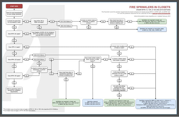
If you're a fan of these cheatsheets and flowcharts, check out the Toolkit. For a limited time we've set up an instant-download of all the latest cheatsheets immediately when you subscribe. If you're already a subscriber, great! Just login for the link. Hope you have a great rest of your week! Quick but big post today - we've just completed our most-requested tool to date - I'm happy to announce the System Estimator. We've taken the Remote Area Analyzer (free online, here), added in hose allowances, main losses, elevation losses, riser details, and underground for an estimator tool that allows k-factor, spacing, density, system type, etc with updated system pressure and flow demands, all in real-time! Check out a very rough video snapshot of real-time pressure and flow updates here: If you're a toolkit subscriber - great! Get the new tool right now by clicking the download link below: Have you ever needed to do a quick estimate for a job, and not had a couple spare hours to lay out and calculate a system?
Even for a very basic remote area, laying out sprinklers & pipe, adding fitting, flow, control valve, and backflow losses, a source, and then hydraulically calculating is smoothly - easily can take an hour or more. Now take that same design and change it to a dry system, or at a different density. If you're like me, tweaking sprinkler spacing, k-factors, sprinkler heights, remote area sizes, and c-factors alone can take significant iteration just to get an idea of pressure & flow demand. With this new estimator you can adjust all of those items in one-click, and see the immediate impact of each decision. It's built for estimators, but it can be a very helpful tool for new designers & engineers to quickly grasp design decisions well before a system has to be completely laid out and detailed. Any feedback, let me know! As always, thanks for reading & have a great rest of your week. The community here is second to none - after a post on my personal list of ideas for getting 'unstuck' in hydraulic calculations last week, I received a handful of encouraging emails and a string of great commentary. Being an engineer and a son of two accountants, I can't help but turn those everything into a spreadsheet. With the tips last week and great feedback sent in, here is a PDF tipsheet that includes a quick rundown of ideas to consider when fine tuning and getting 'unstuck' while running fire sprinkler hydraulic calculations. Click the image or link below to download. 
If you haven't already subscribed for tools & cheatsheets like this, you can do so, for free, here. Thanks & have a great rest of your week! Have hydraulic calculations ever kept you up at night?
I can usually tell when I’m carrying extra stress in my life because my nightmares looks suspiciously like a hydraulic calculation that, despite any refinement, just doesn’t calc’ out. Ever had that? I’ll refrain from sharing all my personal issues for now, but if you’re a sprinkler designer or FPE, you’ve had to experience a project where there’s seemingly no way to get the hydraulics in the black. When I initially lay out a project I’ll have a rough idea of pipe sizing and layout type (tree, grid, loop) based on similar projects. I’ll lay out a remote area and ‘rough-in’ the rest of the design so that I can get to hydraulic calculations iterations as early as possible. Iterations? Yes, iterations. If you’re long versed in the sprinkler industry this needs no explaining. If not, the secret sauce of a high-value designer/engineer is all in the refinement and iterations. If you’re a consulting engineer, perhaps you’re less interested in whether a system is efficient and more interested in whether a system ‘can work’. If you’re on the install side of the trade, you can earn back good pay and more by calculating systems that are well optimized – that is – perform efficiently, use the right system type, sprinkler type, and allocate pipe sizing appropriately. This week I’m running down a quick list on potential avenues to consider when you’re working through those calculations and need ideas on tweaks that could help. A quick disclaimer – hydraulic calculations are an important part of ensuring that the systems we design will be effective in suppressing a fire. The categories below are important aspects to consider when conducting hydraulic calculations – not corners to cut – but rather ideas to get unstuck in optimizing a sprinkler system. System Type Probably most important consideration is the system type (grid, loop, or tree). Dry and pre-action systems have limitations (no grids allowed), but if a facility is big enough then moving to a loop or grid configuration may significantly help the system perform more efficiently (ie: smaller size pipe). Sprinkler K-Factor This perhaps could be the most often-overlooked impact on a sprinkler calculation. Are you using the right k-factor for the job? If you’re always using K5.6 until you get into storage applications – there are better tools for the trade. Adjusting the k-factor based on the density and sprinkler spacing directly impacts the starting pressure within a hydraulic calculation. If you haven’t tried it yet, use this tool that’s a part of the Toolkit to find the optimal k-factor for your job. Pipe Sizing Perhaps the most obvious and classic go-to is adjusting the size of pipe diameters. The larger the pipe diameter, the easier (less friction loss) the water will experience when passing through the pipe. Pipe Schedule This isn’t always negotiable – many specified projects will stipulate a pipe wall thickness – but be cognizant that the pipe schedule is (1) correct for the job, and (2) is considered in the hydraulic calculations. I had long underestimated the impact that pipe schedule had on hydraulic calculations, but it’s major. Schedule 40 and Schedule 10 can have a major impact. Change from Schedule 10 to Schedule 40 and you’ll increase friction loss by 24%. See the impact on friction loss with the Friction Loss Calculator as part of the Toolkit here. C-Factor Also not a negotiable part of a project – c-factor directly relates to the friction loss under the Hazen-Williams method of hydraulic calculations – its nonetheless important to get correct. How can you improve the c-factor? The pipe type (plastic, copper, ductile iron or steel) and system type (wet, dry, pre-action, deluge) will impact the c-factor. One project I worked on had major challenges, including a quadruple-slam of dry system, sloped roof, tall roof, and poor water supply. The only suggestion we had to avoid a fire pump was to insulate and heat the building such that a wet system could be used. That change had a number of impacts, but the c-factor change from 100 to 120 for the pipe had a major bearing on the new system working. One major change that’s coming to the 2022 Edition of NFPA 13 is allowing a C-Factor of 120 to be used on new dry systems that are installed with nitrogen. I’ll be sure to explore this in more depth when the time comes. Sprinkler Spacing Are your sprinklers maxed out at the greatest possible coverage area? In some applications, this can hurt more than it helps. Yes, we might save on the cost of material and labor with a reduction in sprinklers, but reducing the area per sprinkler in a very tight calculation can have a positive impact with starting pressures and the densities achieved. See the density vs. k-factor calculator as part of the Toolkit to see the impact with various sprinkler spacings. Remote Area Size There are some reductions in allowable remote area size in NFPA 13. A common one is the quick-response reduction, which allows a smaller remote area size for systems which have low(er) ceilings and quick-response sprinklers. See the impact of remote area with the Remote Area Analyzer here. Water Source Height An often overlooked part of the calculation that has a major bearing on the result is the height of the water source. Many systems are designed based on a fire hydrant flow test. Is the elevation of that source accurate, relative to the jobsite? I once worked on a job where a submittal showed the source (city water grid) to be at an elevation of 0'-0" relative to the first floor of the building. I charted google earth and paid close attention to the listed source from the flow test report. While a hydrant existed about at ground level elevation, the actual static/residual hydrant where the test results were gathered was at an elevation 27-feet below the project grade. It was a substantial hit to the hydraulic calculations (all calculations failed with the correct elevation shown). Backflow Preventer Loss On many systems the backflow preventer presents the worst pressure loss for any single piece of equipment on the system. It's easy as a designer to input a curve or a conservative static loss, run the calculation, and not return to the backflow preventer. However, if you're seeing high pressure losses, shop around. There are a variety of backflow preventers on the market, and using backflows that are straight (horizontal/vertical, not N- or Z-type) and use OS&Y valves instead of butterfly valves can offer some hydraulic savings. There's a whole database we've created on available backflow preventers as part of the Toolkit here: BACKFLOW DATABASE* Valve Types Just like backflow preventers, valves introduce pressure loss into the system. An OS&Y valve will remove the water-blocking paddle from the water stream, allowing water to pass through mostly unimpeded. Other valves like butterfly valves leave the paddle in place, causing some pressure loss. Sprig, Drop, On-Pipe, Flexible Drop & Return-Bend Configurations Ever looked at the difference between using sprigs and not using sprigs (on-pipe fittings or outlets) has on a calculation? If you're at a higher density, it can be significant. Hydraulic calculations are usually not a driver in whether sprigs are used, or whether return-bends vs. side outlets vs. bottom drops are incorporated - however - these have an impact on the calculations and can introduce pressure loss in between the sprinkler and the branch pipe. One notoriously high friction loss arena is use of flexible drops, which can add pressure loss with equivalent 1-inch pipe lengths of 20-70 feet of pipe. These friction losses can vary significantly among manufacturers and models. Riser Nipple & Sprig Diameters Have a storage calculation with high densities and a high sprinkler k-factor? It may be worth adjusting the sprig diameter to see the impact of the 1-inch diameter pipe. Similarly, riser nipples in-between a main and branch line bear the full flow from the branch line to the main. These pieces, while many times shorter than the spacing between sprinklers, can still introduce a pressure loss to the system that a stepped-up diameter can help. Special Application Sprinklers Lastly - is there a sprinkler specifically designed for the application you have? Many manufacturers over many decades have dialed-in and created sprinklers that are built for specific purposes (special application sprinklers). These product listings can allow different starting pressures and design criteria, which, as a whole, can help reduce the water burden on a system. Two that I often use that come to mind are residential and attic special application sprinklers. In both cases, use of those sprinkler types within their respective hazards dramatically reduce the water required at the remote area, thereby allowing smaller mains and equipment back at the riser. See a list of all available sprinklers on the market (filter & search) on the Sprinkler Database in the Toolkit. What Else? In the next post I'll look to put together something that's a little more handy as a checklist for entry and intermediate designers. In the meantime - what am I missing here? What aspect of hydraulic calculations do you think are often overlooked yet carry a big impact? |

ALL-ACCESS
SUBSCRIBEGet Free Articles via Email:
+ Get calculators, tools, resources and articles
+ Get our PDF Flowchart for Canopy & Overhang Requirements instantly 
+ No spam
+ Unsubscribe anytime AUTHORJoe Meyer, PE, is a Fire Protection Engineer out of St. Louis, Missouri who writes & develops resources for Fire Protection Professionals. See bio here: About FILTERS
All
ARCHIVES
April 2024
|
 RSS Feed