
|
This week we have progress and are continuing the effort to create an open, easy-to-edit and easy-to-digest basic sprinkler specification. The first week we touched on the need and developed the general criteria. Last week we expanded on the feedback and introduced equipment to the spec. This week we’ve adapted the specification based on feedback from you (thank you!) and are adding in the ‘means’ portion of the specification. THE GOAL OF A SPEC Our goal here is to have a simple baseline specification that answers the most critical questions which a specification should resolve, and otherwise stay out of the way. A great specification should:
OUR INTENT This specification is not intended to replace consultant’s own customized specifications that are well thought out, intentional, relevant, and updated. They are intended to be a free, easy-access alternative to stand in for specifications that are boilerplate, don’t answer critical questions, or haven’t been updated in twenty years. Based on your feedback, this week’s updates include references to water storage tank, using an imperative tone, cleaning up portions of the system, adding standpipe and dry system references, and incorporating your comments.  YOUR INPUT NEEDED Here are the key areas I'd love to hear from you about as we take the next step in building the specification:
THE 'SPEC GENERATOR' IDEA One of the ideas we threw out initially along with an open-specification was a new specification generator. The basic concept is that you'd play a game of "20 Questions" and in less than a minute you'd have a fully-edited specification. Most contractors I speak don't believe that specification editing actually takes any time at all - mostly because they're used to reading copy/paste boilerplate specification. But consultants know that a well-edited, accurate specification can take hours on each project between selection, making the edits, QC, formatting, and updates. Depending on how many people are involved in the process and how complex the job is, this sometimes takes 2-4 hours just in specification editing. The concept we're working on in parallel with this is a basic specification generator that does the editing for you, and provides meaningful tips on editing along the way. My intent is to pop this right into MeyerFire University with the other tools there about as soon as we're done with the open-spec. Here's a short video on the concept: Don't forget to comment below on the questions we posed. I am very grateful for your input and willingness to push the industry ahead, as always! - Joe
3 Comments
Last week I worked error propagation for a pitot measurement to flow rate conversion.
Because it's a measurement, there is a natural level of precision that we can only estimate that depends on the precision level of each of our measuring points (our tools). Yet, we (maybe just I) often overlooked the concept of measurement error. In this tool (below), I've incorporated the error propagation to suggest a range for the result instead of what we typically express as a near-certain test measurement. So, now, you can convert a pitot pressure into a flow rate and immediately get the error tolerance based on the tools you've used and measurements you've taken. Hardly any additional work. While it may sound trivial, knowing what amount of tolerance we are actually achieving in a test measurement could be the difference between a test pass or test failure - especially in regards to fire pump testing. Check out the tool below, and let me know what you think! It has an IP and SI version built in (I'm finally catching on).
If you're a member of MeyerFire University this will be added to the iOS and Android app automatically.
Thanks and have a great rest of your week! - Joe This week I'm happy to debut an update to one of our popular tools, the K-Factor selector, which is a part of the Toolkit. This tool quickly calculates the actual pressure and flow across different types of sprinklers. It's helpful when we're trying to select the best-possible sprinkler for a hazard. Even for light hazard areas, a standard k5.6 sprinkler may not be the 'optimal' sprinkler, from a hydraulic perspective. We touched on this when looking at whether the flow through a sprinkler is governed by the density and area or by the k-factor and minimum pressure. In short, the minimum flow through a sprinkler can be driven by the coverage area of the sprinkler multiplied by the density of the hazard, or, it can be driven by the k-factor of the sprinkler and the minimum pressure that sprinkler requires.  In either case, it's important to make a quality selection for the k-factor if we want to reduce the required pressure and flow that a system will demand. Less flow usually means less friction loss, which can result in more efficient systems and smaller pipe sizes (saved cost of material and labor).
The updates to this tool make it mobile and tablet friendly, and also now clearly indicate what the 'optimal' sprinkler k-factor is for flow and for pressure (hint: they're not always the same). If you're a Toolkit user, just click the image above to see the updates. Thanks! It's been too long since our last cheatsheet! Happy to bring about a new one to the table today. One number that I seem to always need to crunch when laying out or reviewing fire sprinkler systems is the remote area adjustments, and the minimum width of a remote area. This applies specifically to the Density/Area method of Hydraulic Calculations in NFPA 13. The formula is simple enough, w = 1.2 x sqrt(remote area size), where w is the minimum remote area width, and the remote area size is our final adjusted remote area that we're using. Now for a routine calculation with a remote area of 1,500 sqft, I pretty much have the 46.5-foot area width memorized. Why is it important? The minimum width dimension tells us how wide our remote area needs to be. It's the dimension parallel to the branch lines, that captures as many sprinklers as it can along the branch line. 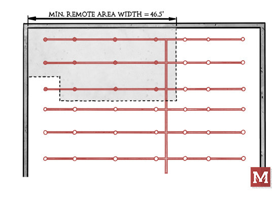 We take this minimum area, see how many sprinklers this area covers, and round up to the next whole sprinkler. It's our minimum width dimension that we're not allowed to reduce. The 46.5-foot dimension might be easy enough to remember, but what about when a remote area is reduced using the quick-response reduction? What if the ceiling is also sloped? Adjustments to the remote area are a process on their own, and each have implications for the minimum remote area width. If you're using our Toolkit you already know we have tools that will compound the calculations for you. Our Quick-Response Reduction tool will adjust the remote area size based on the ceiling height, and our System Estimator tool will adjust for quick-response, sloped ceilings, dry and pre-action systems, high-temperature sprinklers, and more:  But, there are still times where I just want to quickly glance at my remote area size and translate that into a minimum width. That's what today's cheatsheet is all about. This quick reference PDF helps address a few things:
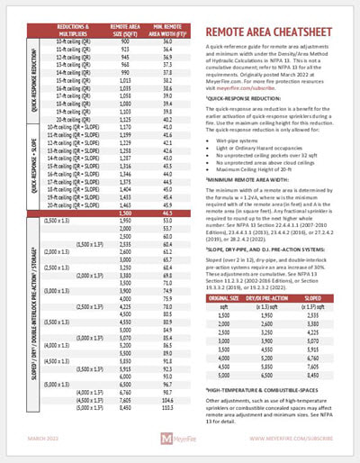 I hope this one is helpful for you as conduct or review hydraulic calculations on your projects. Any tips, feedback or improvement ideas, be sure to let me know.
Thanks & have a great rest of your week!
Today is a pretty big day in MeyerFire-world.
I've spoken with contractors, consultants, plan reviewers, educators, insurance carriers, installers, inspectors - and we all continue to come back to one big issue that is holding our industry back right now. We need to develop new talent. For the organizations that are busy and growing - we need more help, and we need knowledgeable help. When we look out even a little into the future, even just 2-5 years from now, the problem will be compounded. Call it the Silver Tsunami, the Experience Exodus, the Golden Goodbye, or whatever other name the kids come up with - our industry has already lost a lot of experience to retirement, and that will only continue as many of the remaining Baby Boomers look to complete their careers. We need to develop new talent. We need something that can resonate with today's Gen Z. We need engagement, and a way to not just train in a two-day or two-week sprint, we need something that can help people new to the industry learn every single day, year-round. Around here we've thought and debated and circled on the idea for a solid couple years. I'm excited to say that we finally have the platform that we have built specifically to help develop new talent in the fire protection industry. We're calling it MeyerFire University: It's an all-new training platform built for those with 0-3 years experience, and covers technical topics like fire suppression, fire alarm, code, life safety, and specialized systems; it covers production topics like plan preparation, drafting, modeling, and plan review; and it covers business & career topics as well. It's everything we wish we had when we started, delivered in bite-sized, highly-visual video clips that are delivered daily and on-demand. Today is our "Soft-Launch". If your organization finds that you also have this need to help train and develop new talent - and you want to join in on this platform early - now is a good time to do so. We've only been in full production on our video content for a month and our platform is growing by five new video modules each week. If you're wanting to be an early adopter - we have a couple ways of saying thank-you and making sure the platform is worth your team's time. To get a quote & more information for your organization, visit:
This has been a dream we've worked towards for years now, and I'm thrilled that it's finally coming to light and can soon start helping teams like yours shine.
Thanks for your time and being a part of the community for better fire protection! It's been something that has been requested here and there about the Toolkit, and I'm happy to say we've finally come around and made this happen. I apologize that its taken way too long to get some of this training out. If you're a Toolkit user (thank you!), we now have a welcome series of weekly emails that explores each tool in a little more depth. Some emails are articles exploring some of the topics, some emails include videos explaining the tools in a little more detail. You can always unsubscribe at any time. To sign up for this free email series, you can do so here: If you don't already have our whole set of tools, check it out here: www.meyerfire.com/toolkit. Happy to say it continues to do well thanks to your feedback and referrals! That's all for today - thanks and have a great rest of your week!
The fire sprinkler database is coming up on its third year in existence; it originally took hundreds of hours of research and plenty of updates, but we're happy to say now that we've upgraded the database to include better search, sort and filter capabilities.
The database is a collection of over 1,500 fire sprinkler models on the market today. Even with a select number of manufacturers, finding just the right type of sprinkler with correct spacing and minimal pressure demands can be tough. The database was built to get answers in seconds - with links directly to manufacturer websites & data sheets. See a quick update video here: The database is part of our Toolkit package. More information about that here. Have a great rest of your week! One of the most-requested tool features was not technical - we wanted color! I'm happy to say that with today's new updated release of the MeyerFire Toolkit we now have just that - different color options to match your company's look:  It sounds incredibly simple, but this one took a little while to work out the kinks. At least we rocked out to 90's jock jams while doing the updates, which may or may not have influenced the bright color choices. To get this update, download the latest version of the Toolkit here: www.meyerfire.com/download. If you aren't a Toolkit user, you can get a copy here - www.meyerfire.com/toolkit. Thanks & have a great week! A quick update this week - back in 2018 I put together a flowchart for when sprinklers are required in closets. It was nice and had some nice feedback, but it only pertained to the 2016 Editions of NFPA 13, 13D, and 13R. This week I went back and made some major updates for references from the 2002 through the 2019 Editions for each of these standards. This cheatsheet is a little more printer-friendly (11x17) and simplified to the NFPA 13, 13D and 13R standards. 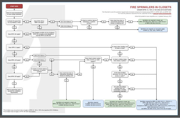
If you're a fan of these cheatsheets and flowcharts, check out the Toolkit. For a limited time we've set up an instant-download of all the latest cheatsheets immediately when you subscribe. If you're already a subscriber, great! Just login for the link. Hope you have a great rest of your week! Quick but big post today - we've just completed our most-requested tool to date - I'm happy to announce the System Estimator. We've taken the Remote Area Analyzer (free online, here), added in hose allowances, main losses, elevation losses, riser details, and underground for an estimator tool that allows k-factor, spacing, density, system type, etc with updated system pressure and flow demands, all in real-time! Check out a very rough video snapshot of real-time pressure and flow updates here: If you're a toolkit subscriber - great! Get the new tool right now by clicking the download link below: Have you ever needed to do a quick estimate for a job, and not had a couple spare hours to lay out and calculate a system?
Even for a very basic remote area, laying out sprinklers & pipe, adding fitting, flow, control valve, and backflow losses, a source, and then hydraulically calculating is smoothly - easily can take an hour or more. Now take that same design and change it to a dry system, or at a different density. If you're like me, tweaking sprinkler spacing, k-factors, sprinkler heights, remote area sizes, and c-factors alone can take significant iteration just to get an idea of pressure & flow demand. With this new estimator you can adjust all of those items in one-click, and see the immediate impact of each decision. It's built for estimators, but it can be a very helpful tool for new designers & engineers to quickly grasp design decisions well before a system has to be completely laid out and detailed. Any feedback, let me know! As always, thanks for reading & have a great rest of your week. |

ALL-ACCESS
SUBSCRIBEGet Free Articles via Email:
+ Get calculators, tools, resources and articles
+ Get our PDF Flowchart for Canopy & Overhang Requirements instantly 
+ No spam
+ Unsubscribe anytime AUTHORJoe Meyer, PE, is a Fire Protection Engineer out of St. Louis, Missouri who writes & develops resources for Fire Protection Professionals. See bio here: About FILTERS
All
ARCHIVES
July 2024
|
 RSS Feed