
|
We've made a few updates to our Trapeze Calculator tool - primarily with code references and table updates from the 2013 through 2022 Editions of NFPA 13. The tool now features updated references for the different editions of NFPA 13.
QUICK CALC With only a few "knowns" (pipe diameter and schedule, and distances to nearest structure), you can now quickly calculate the required section modulus, visit options for the trapeze bar, and see these options schematically in a scaled section view. MULTIPLE PIPES? Do you have multiple pipes on a trapeze? Calculate the section modulus required for each, add the two moduli together, and simply override the Section Modulus Required value below to see your options.
1 Comment
This week I've updated our Quick-Response Remote Area tool, which quickly takes a few considerations into play and reduces the size of a fire sprinkler design area based on the Quick-Response Reduction that's allowed in NFPA 13. This new free version incorporates references in NFPA 13, 2022 Edition.
Suppress Early, Suppress Less The concept behind reducing the calculated hydraulically remote area in a fire sprinkler system is entirely based on fighting a more minor fire earlier in the development of the fire. There are a handful of factors that contribute to the timing of sprinkler response (a good future discussion), which include the thermal sensitivity, sprinkler temperature rating, distance of sprinklers relative to the ceiling, sprinkler spacing, ceiling height, and dynamics of the fire itself. The reduction in the hydraulically remote area is based upon comparative tests of quick-response spray sprinklers against standard-response spray sprinklers. According to the NFPA 13 handbook, the tests demonstrated that the earlier the water is applied to the fire, the smaller the fire and, ultimately, the fewer sprinklers needed to activate. Not Universally Accepted While the remote area reduction has been included in NFPA 13 for years, it is not universally accepted. Many engineer specifications don't allow the reduction, and design standards for significant organizations such as the Department of Defense (UFC 3-600-01) don't permit it either. Why not accept the remote area reduction, if NFPA 13 includes it? Like other elements in hydraulic design for fire sprinkler systems, not using the remote area reduction provides an additional safety factor to the system. Additionally, since the quantity of sprinklers relates to the quantity of water flowing in the system, main sizes are directly impacted by using or not using the quick response area reduction. Building owners may opt to not want to reduce the remote area to preserve reasonable (larger) main sizes and give themselves flexibility on building modifications and sprinkler system changes in the future. Quick-Response Area Reduction Calculator This quick calculator is in part a checklist of prerequisites to reduce the remote area on a fire sprinkler system, in part a method of showing your work, and in part a quick calculator on determining your final remote area size. Don't see it below? Give it a try here. I hope you find these tools helpful. Free ones are available on the TOOLKIT dropdown at www.meyerfire.com. If you're a MeyerFire University member, you get all these right in your iOS or Android app too. Thanks, and hope you have a great rest of your week! - Joe I’ve read that we tend to overestimate what we’re able to achieve in short time spans – days or weeks – but we tend to underestimate what we’re able to achieve in long time spans – years. I absolutely believe that to be true. Very small but consistent steps of progress over years add up; and much of the direction has simply been from listening to our ongoing challenges and trying to think about novel ways of addressing those challenges. NFPA EXPO Two weeks ago, we hosted our first MeyerFire booth at the NFPA Conference & Expo in Orlando. What a hit! I’m so thankful to those that stopped in and checked out the latest of what we’ve brought to life. I wanted to share a bit about that here. SHORT ATTENTION SPANS? While learning would be a lot more fun if it was all simply a video game – there’s a fair amount of data to back up that concept. We dog on the youngest generation for short attention spans (side note: dogging on the youngest generation has been a documented tradition for over two millennia). We harp on the youngest generation for not wanting or being willing to learn the same way ‘we’ did (books, asking questions, mentoring, willing to get dirty, or insert-whatever-old-method-here). Yet, that same cohort can spend hours without eating to hyper focus on video games. It’s not an attention span issue. It’s an engagement issue. And before we criticize new learners for not being willing to pay attention, remember that new learners today are working from a completely different set of resources than was available even a decade ago. We live today in a world of information abundance. INFORMATION ABUNDANCE We have more information available in our pocket today than the President of the US did just 15 years ago. There is a how-to on nearly everything online. Accessible, immediate, helpful, concise. Then we get to training in our arena, and the delivery is still much the same that it was literally thirty years ago. Maybe it’s not the new learners who aren’t taking to the same information as we did some time ago. Perhaps it’s those new learners today, rightfully, have a much higher level of expectation for learning than in years past. Maybe it’s the delivery, the content, the accessibility, and the engagement that really needs to step up and deliver in a way that’s relevant to today. ENGAGED LEARNING TO MEET HIGHER EXPECTATIONS It's that concept – engaged learning in an immediate, accessible way – that led us to create virtual interactive simulations. It was not easy in the least and is well into over a thousand hours and a major financial investment – but the result is a learning environment that’s always available, immediate, at your fingertips, and engaging. At NFPA we debuted our new Fire Pump Room: an interactive environment with an incredible amount of detail. This is live at MeyerFire University today. The Fire Pump Room is a virtual space that runs a fully balanced supply-side hydraulic calculation in real time.  It has a working test header with hoses, an operable fire pump, both analog and digital pressure gauges, operable OS&Y and butterfly valves, inspector’s tests and main drains, LED indicators on monitor modules, working fire pump and maintenance pump controllers, and a functioning and controllable supervising fire alarm control unit. There are over 1,900 dynamic elements in this space alone, that respond in real time. Within this room, you have all the equipment and capability to run a complete fire pump acceptance test and backflow forward-flow test. At the NFPA Expo, we hooked up an XBOX controller and played it live. It was awesome! I’d like to share here a bit of the level of detail we included to make this as authentic as possible – so that it’s relevant and helpful for learning. Here are a few details that I found most interesting when building this – OPERABLE OS&Y VALVES  The OS&Y valves are fully operable; note the movement of the stem, handle turning, the LED indicator light on the wall, and even plunger movement once it falls out of its groove. FLOWING WATER THROUGH HOSES  The test header features six different hoses with water that flows based on the position of the valve. Even the valve coefficient changes as it would in real life – and the trajectory of the water throw is based on the calculated physics of the fall of the water based on its velocity. OPERABLE BUTTERFLY VALVES  Butterfly valves operate similarly to the OS&Ys; they handle movement, indicator paddle, and LED indicator light. We’ve even matched up audio (separately) for the piezo buzzer at the FACU. INSPECTOR'S TEST & MAIN DRAIN  The combination inspector’s test and main drain are operable, and when they engage the waterflow switch for more than 30 seconds, it’ll push the fire alarm system into alarm. GAUGES  With every operational change, each gauge updates based on the results of the real time, balanced hydraulic calculation results. We’re able to see city pressure, backflow downstream, suction, discharge, riser pressures, and sensing line pressure. FIRE PUMP CONTROLLER  The pressure maintenance pump controller offers a digital gauge on the sensing line, but the main controller has a readout on amperage, voltage, RPMs, and sensing line pressure. Just don’t kill the power to it! FIRE ALARM CONTROL UNIT  Finally, everything is monitored by the fire alarm control unit. Working strobes, horns, bypass mode, silencing features, and reset functions just like you’d expect from your favorite brand. THE CHALLENGE  In this simulation, we’ve put in three different challenges for the user to operate, flow correctly, and readout. Our next step is to build upon these with various ITM situations. THE MOST-COMMON QUESTION
One of the most-common questions I get is ‘what software did you use for this?’ Unfortunately, there is no magic software to bring this to life. This simulation alone has nearly 6,000 lines of HTML code to operate the 1,900 dynamic elements to bring this all to life. Many hours, creative hacks, and testing and retesting hydraulic loops until all the different scenarios balanced and responded correctly. The feedback on it has been incredible, and I’m very excited to put more into researching and developing this side of what we do. Will we build on these scenarios? Absolutely. Will we be building new ones, with different types of systems? Absolutely. Is it going to take another 1,200 hours to bring more of these to life? Absolutely. That said, I think the usefulness of these for learners who don’t get out to the field, don’t travel to see the labs, or aren’t even allowed to operate the equipment (I’m looking at my former self for this one) – is palpable. This could be a great thing for our industry. EDUCATION PROVIDERS If you’re an educational institution with students who could benefit from this – please get in touch with us. We spoke with several universities at the Expo, and I think this (alongside the rest of MeyerFire University) could be a major boon for undergraduate students. MANUFACTURERS Same with manufacturers who may want to help develop ultra-realistic systems for better learning; please get in touch with us. There could be opportunities to build things for you that could help learners, your own staff, and your own customers in parallel. THANK YOU There has been a ton of work to make this happen over the last year. Other than a few people, much of it was under a rock until we knew that we could pull it off. Thanks to those who have shared challenges, brainstormed with us, given feedback, and continue to support what we do. The better we can serve you – the better professionals in our industry will be able to operate. Hope you have a great Fourth for those in the US (or Canada day if you’re our friends up north) – and have a great rest of your week! - Joe Much of the MeyerFire.com concept started as a simple website around P.E. Exam preparation – that is – helpful articles, resources, and a book to help us all pass the Fire Protection Principles & Practice of Engineering Exam (P.E. Exam). We still support that effort today, now about nine years later. We have a book (the PE Prep Guide, now in it’s 8th Edition) and the PE Prep Series (20 weeks of online practice questions). I’m very excited to announce today that we’re upgrading that experience in a very big way in incorporating and upgrading our PE Prep Series into a complete exam prep experience inside MeyerFire University. WHY ADD PE PREP TO MEYERFIRE UNIVERSITY? Everything for the PE Prep space has simply been listening to you. I personally was very frustrated with the lack of quantity of materials when I took the Fire Protection P.E. Exam in 2014, and the following year sold maybe a dozen copies of a formula sheet I put together to help organize and clarify different formulas. Well, in listening to those who used it – the next year we added 100 questions and wrapped the formulas into the first edition of the PE Prep Guide (2016). That book was rough! Very rough. We had something like 20 to 30 different errata updates all based on questions and feedback about the book.
But – we listened, improved, and with a lot of community help – the book improved. In 2017 there were still many updates that needed to be made. Every mistake was like a little knife jab in my side – I felt every one. But I listened, re-wrote, published the errata and updated the book each year. The PE Prep Guide has turned into the #1 selling book in the Fire Protection PE Prep space. You might recognize it on the shelf of someone who’s taken the exam in the last few years. It’s helped many people pass the exam. We did the same with the PE Prep Series. It came about in 2018 when feedback kept coming back about more practice – more questions – more immediate feedback. That, and, we wanted a fun way to know where we stand as things progressed. That’s where the PE Prep Series came from. And now? REAL-TIME ANALYTICS, GUIDED STUDY, BETTER PRACTICE Again, based on your feedback – we’ve sought ways to give you real-time analytics across the different subject matter. We’ve sought ways to help guide your study to be more productive and see more immediate improvement in weaker areas. We’ve sought ways to help you build towards the PE Exam at any time, rather than a couple months out of the year. Why couldn’t an EIT be working towards the PE all the time? Over the course of a few years without a major time burden, but rather be learning, growing, and increasing understanding all the time? What if someone coming out of school could immediately see a path to the PE? And, at any time, know where they stand and the likelihood of them passing the exam today? That’s the line of logic where we ventured – and the answer is that we have that data. We now know what the odds of passing look like based on how you prepare and grow. And we can give that right back to you with each step along the way. That’s where I’m excited to announce that we’ll have an entire PE Prep Series (learning content, practice questions, guided self-study, worked solutions, live analytics, leaderboards, and exams) right inside MeyerFire University – at no extra cost.  In the next few months be on the lookout for course material specific to the Fire Protection PE Exam with MeyerFire University. Our current timetable is to have all of our added content on MeyerFire University by the end of September 2024; plenty of time to learn and grow for the April 2025 Exam. BUT JOE - I’M NOT INTERESTED IN THE PE? Maybe the P.E. Exam, specifically, is not of interest to you. That’s OK! The hope of having the prep material available (again, at no additional cost) and living inside of MeyerFire University is that you can access it. You can test yourself against FPE’s and FPE candidates. You can learn as much as you want in that space. The exam? It’s a credential. A big one – but it’s just that – a credential. If you want the knowledge, the understanding, the personal growth? Well – that’s our whole goal of MeyerFire University to begin with. Unlimited learning. If you’re in the back corner of the office and aren’t exactly getting the opportunities to grow or train or be mentored – well, we’re calling your name! We want you here; learn what you want to learn, when you want to learn it. Challenge and invest in yourself. That’s entirely the point of creating the platform to begin with. I am beyond excited about creating a resource like this – it’s exactly what I would have wanted to prepare for the exam. To challenge myself, know my standing (immediately), see a path to pass, and have a little fun with it along the way. WHAT ABOUT NICET? What about NICET? We love NICET; and we hear you when you’re asking for more and more in that space. We’re listening, and we’re working towards it all the time. There’s not a timetable that we’re ready to announce just yet, but do know that if it’s what you want to see, then it’s what we want to create. A BIG THANK YOU A big thank you, as always, for the ideas, tips, constructive feedback, and community support. This entire platform wouldn’t exist without you and the passion that we collectively have for the fire protection industry. We’re excited to push the envelope and help us all do great work in fire safety in the world. Thanks! - Joe Conventional training tends to be boring. I don't know that this is really news to anyone. I know it to be true because if you tell a stranger on an airplane that you're in training, their eyes start to glaze over before they go to use the restroom and never return. I won't say whether or not this has happened to me. Well, the learning, skill, and real knowledge part of what training should be is extremely important. With our shortage of skilled professionals and the ever-increasing demand for better fire protection, we need it now more than ever. What doesn't fail to keep our attention? Video games. It's engagement. Interest. Interactivity. That's the inspiration behind what we've put over 1,200 hours and counting into our latest 360-degree simulated environments. It's learning by engaging; yet accessed anywhere at any time.  New Fire Pump Room Simulator on MeyerFire University On this coming Monday at the NFPA Expo in Orlando, we're debuting our latest 360-degree simulation that'll also run live on MeyerFire University. It's an immersive virtual fire pump room where you can control valves, see the supervision, see voltage and amperage loads, flow hoses through the test header, check fire alarm supervision, and even test yourself in three different challenges inside the environment. We're excited, and this is just the beginning of what's to come in the learning space. What's the #1 best way to learn? Go out in the real world with a skilled mentor, walk the jobsites, see the tests, and get firsthand experience. What's the second-best way to learn? Spend that same time and go to ten or twenty different virtual job sites and challenge yourself in ways that are impractical or impossible in the real world. We want uninhibited, engaging learning - because that's the only way for the information to 'stick' and transition from 'hearing' to 'knowing.'  New Fire Pump Room Simulator on MeyerFire University NFPA EXPO
If you're in Orlando next week for the NFPA Expo, check it out and play it with us at Booth #404. I can't wait for many of you to see it in person. If you're not attending and are already at MeyerFire University, look for your update email Monday morning with links to the new simulation. Then, let us know what you think right on the 'Discuss' page for the simulation. We can't wait to hear your thoughts. MEYERFIRE OPPORTUNITIES Related to this, now's probably a great time to iterate that we have multiple ways for you to get more involved in what we do in the learning space - writing, editing, teaching, modeling - by joining us in paid roles. Are you all about impacting the industry? Are you a detail-oriented person? Are you the creative type? Good at mentoring? Like creating games? Like to write fiction on the side of reviewing suppression or alarm systems? Great at modeling (... the fire systems stuff)? Great at writing? If any of those strike a chord, you might be a great candidate to help us out in part-time roles. Learn more about what we have open today at www.meyerfire.com/openings. Thanks, as always, for your interest in bettering the industry and for being part of the community you've helped build here. Have a great rest of your week. - Joe First - thank you to all the feedback, comments, and emails that made this possible. This community of professionals looking to help improve the industry is second to none. I very much appreciate the time and input in building this together. A BASIC, OPEN-SPECIFICATION CONCEPT One of the frustrating aspects of bidding a fire sprinkler job in North America is when you're reviewing a job and the specifications that accompany it are simply terrible - boilerplate, don't actually provide any useful information, are conflicting, include irrelevant content, or clearly haven't been updated in decades (list no longer manufactured products). One of the ideas we kicked around and now delivered is essentially an "open source" specification. One that we build and curate together and post for open use. We explicitly do not intend for this specification to replace consultant's specs who already update and care for the industry. The beauty of consulting is providing unique value to your clients - this is absolutely not intended to be the only specification available. Rather, we would hope that it could help provide a baseline open-source template where specifications could at least be of this quality level. OUR GOAL From our collaborations, posts and discussions thus far, we're all really wanting something that is:
There are other goals too, but those seem to be the reoccurring themes. THE DOCUMENT I have highlighted GREEN and BLUE areas where a specific selection needs to be made (one or the other). I have highlighted YELLOW additional alternatives which may be less common than a typical, mid-size commercial job. All portions of this specification would be editable, though the highlighted areas would be of particular concern to change and update job-to-job. DISCLAIMER A very important note here, as is with all tools and resources for the fire protection space. Any information presented should not be relied upon as a replacement for sound engineering judgment. Use only at your own discretion. While we build these to help improve aspects of the industry, we are not and cannot be assume responsibility for use of the specification. For more on our Terms of Service, please visit: https://www.meyerfire.com/terms 
Another big thanks to everyone who helped make this happen. If you're looking for a baseline set of specifications for comparison, for a basic project, or for a consultant who asks - we now have something to share. Towards a better industry - thanks! - Joe Are you tired of specifications yet? If you're a contractor - you've long been tired of bad ones; that's for sure. A month ago now we wrote on the problem: Ideas for Fixing Bad FP Specifications Then we discussed the goals for an open specification, including being helpful, concise, clear and timely. We've now incorporated three weeks of great discussion and feedback, and now this week we have our first complete open-specification. All three parts. All in less than ten pages! What do you like? What doesn't work? What's good practice that you'd generally want everyone to be doing?  I'd love to take your last round of feedback on this (for now) and open up the word document next week.
Thanks for being a part of making positive change happen for the industry! - Joe This week we have progress and are continuing the effort to create an open, easy-to-edit and easy-to-digest basic sprinkler specification. The first week we touched on the need and developed the general criteria. Last week we expanded on the feedback and introduced equipment to the spec. This week we’ve adapted the specification based on feedback from you (thank you!) and are adding in the ‘means’ portion of the specification. THE GOAL OF A SPEC Our goal here is to have a simple baseline specification that answers the most critical questions which a specification should resolve, and otherwise stay out of the way. A great specification should:
OUR INTENT This specification is not intended to replace consultant’s own customized specifications that are well thought out, intentional, relevant, and updated. They are intended to be a free, easy-access alternative to stand in for specifications that are boilerplate, don’t answer critical questions, or haven’t been updated in twenty years. Based on your feedback, this week’s updates include references to water storage tank, using an imperative tone, cleaning up portions of the system, adding standpipe and dry system references, and incorporating your comments.  YOUR INPUT NEEDED Here are the key areas I'd love to hear from you about as we take the next step in building the specification:
THE 'SPEC GENERATOR' IDEA One of the ideas we threw out initially along with an open-specification was a new specification generator. The basic concept is that you'd play a game of "20 Questions" and in less than a minute you'd have a fully-edited specification. Most contractors I speak don't believe that specification editing actually takes any time at all - mostly because they're used to reading copy/paste boilerplate specification. But consultants know that a well-edited, accurate specification can take hours on each project between selection, making the edits, QC, formatting, and updates. Depending on how many people are involved in the process and how complex the job is, this sometimes takes 2-4 hours just in specification editing. The concept we're working on in parallel with this is a basic specification generator that does the editing for you, and provides meaningful tips on editing along the way. My intent is to pop this right into MeyerFire University with the other tools there about as soon as we're done with the open-spec. Here's a short video on the concept: Don't forget to comment below on the questions we posed. I am very grateful for your input and willingness to push the industry ahead, as always! - Joe Last week I posted the start of an open specification and asked for feedback - and boy did you all not disappoint! If you haven't read that post, it's where to start. We laid out a few ground rules about what we're trying to achieve. I genuinely appreciate the review, the comments, and the emails. I'm very encouraged by what we'll be able to build together that can improve things for all of us. Who knew putting together specifications could be so fun? Joking - sort of. As you're able to skim through this updated draft, which now includes Part 1 (General) and Part 2 (Products), here are some of the areas worth paying attention in a little more detail: #1 - CHANGED SECTION NUMBER We've updated the specification section number to reflect that this isn't just a wet-pipe specification; it's intended to consolidate many pages of redundancy into our main goal; a concise, easy-to-read and easy-to-edit specification. #2 - NOTE TO NOT FALL BELOW CODE MINIMUM There's a line added under C in the "1.1 DESCRIPTION OF WORK" that reads "at no time shall work be less than the applicable codes and standards listed below. Proposed alternatives, discrepancies, or questions shall be addressed by written Request for Information." My goal here is twofold; one is that we're protecting the consultant and enabling the contractor to push back in written form. At the end of the day, we need a code-compliant system. The days of turning a cheek or intentionally being above code because a PE said so should be over. The concept with this inclusion in the specification is that if the contractor sees something (anywhere) that is less than code, then they have an avenue to have it addressed formally and an opportunity to clean it up in the project. On the opposite side, the consultant has some relief in that they're clearly not advocating or instructing the contractor to fall below code unless it's in approved written process (such as an approved code-alternative). I hope this to be a win-win opportunity for code-compliance at the end of the day. Like the others - curious on your take. #3 - OPTION FOR PROFESSIONAL ENGINEER TO BE AN FPE OR "KNOWLEDGEABLE AND EXPERIENCED" IN FIRE PROTECTION There's a tangible value to being a Fire Protection Engineer (informally an "FPE") specifically. An over-generalization would be that the Engineer has taken the time to study and pass the Fire Protection P.E. Exam, which itself is no small feat. With that effort and focus (which often takes months of preparation even for seasoned Engineers) there's a line in the sand that speaks to that individual 'owning' fire protection as a key area of focus and effort. Being an Engineer who passed the Fire Protection P.E. Exam doesn't make someone more knowledgeable (outside of learning many new facets while studying) nor better than another Engineer, but it does reflect a certain level of dedication to the fire protection field specifically. That said, we as an industry have far fewer Fire Protection Engineers than Professional Engineers in other disciplines (my at least an order of 10-to-1), so mandating that all shop drawings be performed by or under the purview of a Fire Protection Engineer can be impractical. It's a bigger discussion point for sure, but I've modified the specifications to either call for an FPE specifically, or to mandate a Registered Professional Engineer "who is knowledgeable and has experience in the field of Fire Protection." I'd be curious on your take with this as well. #4 - MOVED QUALIFICATIONS TO 1.5 QUALITY ASSURANCE More of a practical shift here, we had a few requests to move the licensing and qualifications to the Quality Assurance section in 1.5 and out of the Submittal section of 1.4. Seems to make more sense here. #5 - ADDED PART 2 FOR PRODUCTS Since last week we've also drafted Part 2 where we cover Products. This should add a little more 'meat on the bone' and probably queue up plenty of contention points. Let me know what you like and what specifically you would change - all for building a better industry. Click below to view, and thank in advance for helping bring to life a needed resource! 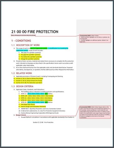 One of the frustrating aspects of bidding a fire sprinkler job in North America is when you're reviewing a job and the specifications that accompany it are simply terrible - boilerplate, don't actually provide any useful information, are conflicting, include irrelevant content, or clearly haven't been updated in decades (list no longer manufactured products). One of the ideas we kicked around a couple weeks ago was essentially an "open source" specification. One that we build and curate together and post for open use. This is the first-stab at what "Part I" of an open, basic fire sprinkler specification might look like. SECTION I OF THREE Typical specifications include three parts:
OUR GOAL From our collaborations, posts and discussions thus far, we're all really wanting something that is:
There are other goals too, but those seem to be the reoccurring themes. We explicitly do not intend for this specification to replace consultant's who already update and care for the industry. The beauty of consulting is providing unique value to your clients - this is absolutely not intended to be the only specification available. Rather, we would hope that it could help provide a baseline open-source template where specifications could at least be of this quality level. YOUR INPUT Where we could really use help here is reviewing this initial (very very first) attempt at Part I a basic open spec. I have highlighted GREEN and BLUE areas where a specific selection needs to be made (one or the other). I have highlighted YELLOW additional alternatives which may be less common than a typical, mid-size commercial job. All portions of this specification would be editable, though the highlighted areas would be of particular concern to change and update job-to-job. Take a look, and let us know your thoughts. If you've been long-frustrated about the prevalence of terrible specifications - then this just might be your opportunity to help us clean up the practice:  Part II, which comes next, identifies equipment and products that are allowed or not. Part III speaks to the execution of the work - that is, any restrictions on what needs to be achieved. THANK YOU Just want to say a big thank you in advance for helping us really impact the industry in a positive way. I and many others very much appreciate it! - Joe |
ALL-ACCESS
SUBSCRIBEGet Free Articles via Email:
+ Get calculators, tools, resources and articles
+ Get our PDF Flowchart for Canopy & Overhang Requirements instantly 
+ No spam
+ Unsubscribe anytime AUTHORJoe Meyer, PE, is a Fire Protection Engineer out of St. Louis, Missouri who writes & develops resources for Fire Protection Professionals. See bio here: About FILTERS
All
ARCHIVES
July 2024
|


 RSS Feed