
|
Things are busy and trending up around here - On Monday of next week the Toolkit officially launches. As a subscriber you'll now be able to use the Toolkit alongside the Sprinkler Database, get all flowcharts as PDFs, and be up to date on the latest tools we're creating and testing around here. Stay tuned for emails next week with the big launch and special offer details.  I started working with fire suppression systems as a bid/spec designer who did both upfront "full-design" as well as "performance-spec" or "design/build" criteria. I'll save frustrations and pet-peeves with this approach for a later time. While I still help architects put those packages together, several years ago I also began helping contractors with permit design, hydraulic calculations, installation detailing, and stocklisting. To say that this foray into seeing the other side of the industry is eye-opening would be an understatement. I've learned so much and perhaps only now realize how much I still have to learn. Here's my top takeaways from pulling back the curtain and working with Oz: 1. Details Are Critical Probably the biggest adjustment when working on installation drawings as opposed to an upfront 'full-design' is that each and every detail is critical. The goal becomes less of "is this a code-compliant, efficient design?" and rather becomes "is this a code-compliant, most efficient design?" What happens when a pipe is fabricated to exact lengths and ends up overlapping with a steel beam by 1/2-inch? Steel beam wins. My buddy in the field now has add a spool piece or re-cut pipe. What happens when you accidentally order unions instead of couplings? You get a phone call. 2. It's Just Theory Until Someone Has to Do It In some ways, living on the 'engineering' side of a project and not the contracting end is dabbling in theory. Even if pipe, fittings and equipment are all shown on bid documents, there's still someone on the back-end putting together installation drawings and a contractor that's looking at it before it gets installed. When you're the guy on the back-end, it's no longer theory. A dimension from a pipe to structure is where it's supposed to go in the field. My point is, my fantasy-world of someone else correcting my schematic layout before it gets installed is no longer there. 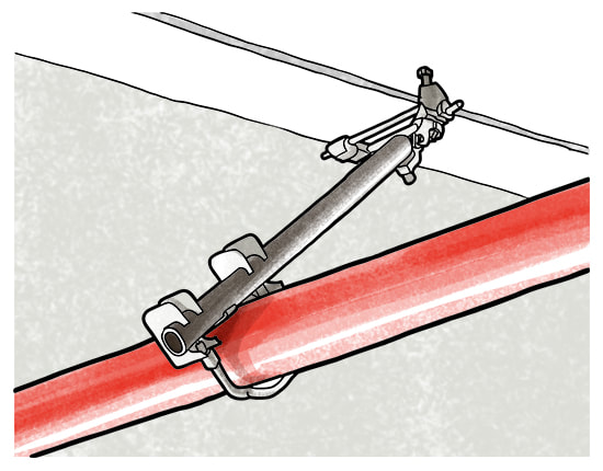 How many components are shown here? I used to see this as a pipe with a lateral seismic brace. After designing installation drawings and stocklisting, I see at least four assemblies with a wide range of options, listings, and details. 3. Preferences Vary Widely Prefer flex drops to hard pipe? What about grooved & welded branchlines over threaded? Want Viking, Vic, Tyco, Reliable, or Globe sprinklers? What about hanger attachments? Preferences vary widely, and while all of the above are code compliant, there is a ton of variation in how different people prefer to purchase and install a system. 4. Ain't Nobody Got Time for This Think architects have tight deadlines? When a subcontractor has a contract held out for long periods of time, only to finally be released for work and in the next breadth asked when submittals will be complete - there's a time crunch. Not all projects designs are under tight timelines and if contracts are released in good time sometimes there's a decent amount of breathing room. But in many cases, my clients need turnarounds as soon as possible. 5. Think Differently Once our drawings were unstrapped from the titleblock and drawing convention (scale, fonts, numbering) typically dictated by the architect - a world of possibility has opened up with flexibility on the documents. Want to know why many shop drawings have details thrown on the same sheet as the plan? It's because the installer may only be carrying that sheet when he or she installs that area. We made the leap a couple years ago to do 100% BIM, whether the job required it or not. In doing so, there's been many opportunities to approach how we construct our drawings differently. When everything is modeled, section cuts become very easy. Want isometrics for risers and complex areas? Done. Why is 1/8-inch scale so prevalent in the shop drawing world? It's about the smallest scale we can do to see everything on a sheet. Traditionally, drafting was labor intensive and each sheet represented a real cost incurred to the designer and thereby the building owner. This resulted in reducing the number of sheets whenever possible. Now, with computer drafting and even more-so in the 3-D world of BIM, scale is almost irrelevant. I find the notion of charging clients by the sheet almost funny now. My life becomes so much easier using 1/4-inch scale - drawings are cleaner, I can show two-line pipe and fittings, annotations take far less time to clean up, and I've yet to have a complaint from an installer concerning the larger scale. In talking to software developers at HydraTEC there's a real sense that BIM will change how we construct drawings. When there's little to zero extra effort to show sections, isometrics, or renderings, then the question becomes less about how much time it takes to show extra detail and instead what presentation offers the best explanation of what we're trying to indicate. It's a really exciting place to be when you're at that point. 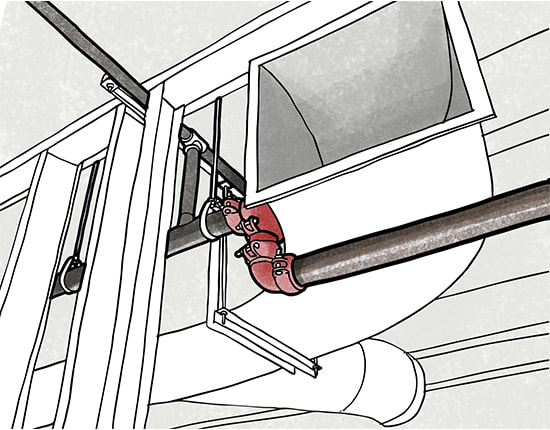 Taking the leap into 100% BIM (building information modeling) on every job has been a challenge, yet now pays off in ways I would have never anticipated with better-orchestrated drawings and flexibility in overall presentation 6. Lack of Information & Consideration Probably my most frustrating lesson is that with many 'design-build' jobs that don't incorporate an engineer tasked with fire protection, there is zero consideration to where fire sprinkler systems and components are going to be installed. I've had many projects put out to bid that don't even state whether a building is going to have an NFPA 13 system, much less space allocated for the sprinkler riser on an exterior wall. For a functional bid, there's a few important details I think would help contractors compare apples-to-apples, and that's for another time but at a minimum should include (1) applicable code, (2) coordinated service entry, (3) flow test information where calculations are needed, (4) pipe specification, and perhaps (5) hazard criteria. 7. Boy There's A Lot to Learn Years ago I was told it takes a solid 6-8 years or so of work in this industry before you gain a foothold in understanding the breadth of the work involved. Malcolm Gladwell, author of the Best-Seller "Outliers", discusses the now famous 10,000-hour rule whereby in order to truly be an expert in a topic, one must amass 10,000 hours of quality experience in that arena. While I hold both of those considerations to be somewhat valid, I also realize after amassing those totals that I still have so, so much to learn in this industry. Please don't think that just because I record and share my thoughts here that I'm in any way more capable or more of an expert in this space than you are or can be. I was on a jobsite yesterday getting installer feedback on one of my latest projects. While walking the job, we discussed at least a dozen different areas that the design could be improved to benefit the installer, allow for flexibility in field adjustments, and ways to route pipe that doesn't upset the other trades. The entire discussion didn't even touch code - there were no code issues - rather it was all about improving design technique for future projects. My joy in sharing this material as someone who is not a refined expert, a Fellow SFPE, or the committee chairman of a major standard is that I can cover the small tips and nuances that we naturally gather and learn along the way. There's so much in the day-to-day where just starting the discussion has value. Know someone who might appreciate this article? Forward to a friend.
Get these weekly articles, for free, by subscribing here. Based on some feedback and good ideas I've been experimenting with graphing fire pump & flow test curves with usable data outputs. Below is the first iteration for drawing a fire pump curve alongside a water supply curve.  Determining ideal fire pump configurations for sprinkler and standpipe systems can be an important part of optimizing fire suppression design Here's the help I could really use from you - what else would be included in your ideal pump curve?
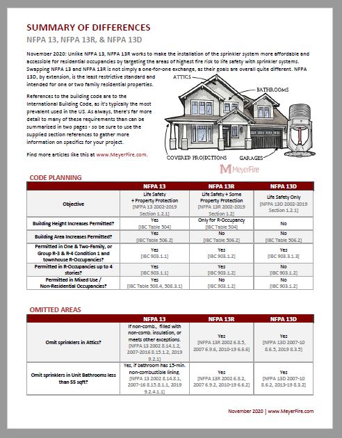
Would you prefer this be on a logarithmic x-axis? Want 175 & 300 psi limit lines shown? Would you want to see at what height in a building the 175 psi threshold would occur - on this graph? System demand and hose? I'm open to any and all ideas - in the end I think it'd be great if this tool was the quickest & best method for summarizing and analyzing fire pump output. Share your ideas in the comments here, thanks in advance! This week's resource was a fun one to put together. Frequent Questions about NFPA 13 vs. 13R I've been asked a handful of times in early project planning phases on whether NFPA 13R would be allowed in lieu of NFPA 13 for a project. In short, the two standards have very different objectives and as a result require very different means. While those who ask are generally looking for ways to save on construction for the project, the differences are important and worth discussing early in a project. Designed for Different Purposes It's important to note that NFPA 13R systems are designed primarily with the intent for life safety (extending the amount of time occupants have to escape a burning building). It's stated purpose is to additional "prevent flashover in the room of fire origin, where sprinklered" (NFPA 13R 2019 1.2.2). Unlike NFPA 13, NFPA 13R works to make the installation of the sprinkler system more affordable and accessible for residential occupancies by targeting the areas of highest fire risk to life safety with sprinkler systems. Swapping NFPA 13 and NFPA 13R is not simply a one-for-one exchange, as their goals are overall quite different. 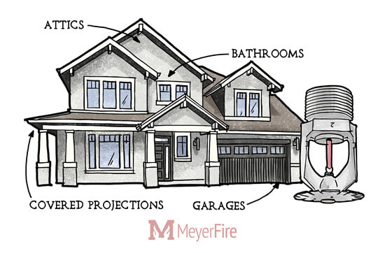 Summary of Differences Here's the summary of differences I use between NFPA 13, 13R, and 13D as a downloadable PDF (at the bottom of this page). References to the building code are to the International Building Code, as it's typically the most prevalent used in the US. As always, there's far more detail to many of these requirements than can be summarized in two pages - so be sure to use the supplied section references to gather more information on specifics for your project. CODE PLANNING
OMITTED AREAS
HYDRAULIC CALCULATIONS
Download PDF Cheatsheet: Save this page as a printable PDF right to your computer. See below for the link:
Want More Like This? Subscribe to these weekly articles, for free, here. This site and the resources herein are created to help you excel in fire protection.
Toolkit Release in a Few Weeks
We're just a few weeks away from the Toolkit release. It'll contain everything that's in the tool now, plus the popular Sprinkler Database and the ability to post any question to the Daily followers. 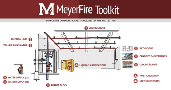
The MeyerFire Toolkit contains all of the quick tools I use regularly, which can be printed or saved as PDFs.
Haven't seen the Sprinkler Database? Watch this quick video: If you've demo'd the MeyerFire Toolkit and have any ideas or suggestions, it's not too late! Please email any ideas for improvement at [email protected]. Vote on the Next Project Here's the top five ideas for next development. Click here to vote below to rate the idea and help guide the direction of tools & resources: Floor-Mounted Obstruction Calculator While it doesn't come up all that often, floor-mounted items can create obstructions for sprinklers just as anything hanging from a ceiling. This calculator is a quick-assessment tool similar to the popular Sprinkler Obstruction Calculator. Access: Free to Everyone / Downloadable for Toolkit Members Fitting Hydraulic Loss Calculator This tool is an expansion of the popular Friction Loss Calculator, but compares loss across various sizes with more output analytics. Trying to decide whether a backflow preventer was calculated correctly? Will you need a 3" or 4" sprinkler riser? Will the choice between various flex drop suppliers matter? This is the tool for you. Access: Free to Everyone / Downloadable for Toolkit Members Fire Pump Database This comprehensive database lists all of the various models of fire pumps available on the marketplace. Just like the Sprinkler Database (currently available to Sprinkler Database subscribers), this database allows users to quickly search and filter all current fire pumps on the markets. Links from the database go straight to manufacturer's websites, product data, CAD details, and Revit models. Access: Free to Toolkit Members Trapeze Hanger Calculator This tool is a quick-sizer with analytics for designing & sizing trapeze hangers for fire sprinkler systems. Access: Free to Everyone / Downloadable for Toolkit Members Next Week This site is created to help you excel in fire protection. It's all about a supportive community & fast tools to help you do great work in fire protection. Next week I'll be covering big-picture differences between NFPA 13, NFPA 13R, and NFPA 13D. If you haven't already subscribed, you can do so here. Have a great week. |

ALL-ACCESS
SUBSCRIBEGet Free Articles via Email:
+ Get calculators, tools, resources and articles
+ Get our PDF Flowchart for Canopy & Overhang Requirements instantly 
+ No spam
+ Unsubscribe anytime AUTHORJoe Meyer, PE, is a Fire Protection Engineer out of St. Louis, Missouri who writes & develops resources for Fire Protection Professionals. See bio here: About FILTERS
All
ARCHIVES
July 2024
|
 RSS Feed