
|
Aside from being the historically-preferred location for canine bladder relief, fire hydrants serve an important function in providing access to a water supply system. 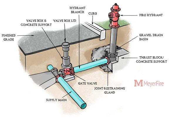 Types Fire Hydrants fall within one of two types; wet and dry barrel. Dry Barrel, as implied, is not water-filled until the hydrant valve is opened. Dry hydrants are overwhelmingly the most popular type of hydrant within the United States to provide insulate using depth to prevent freezing portions of the water supply. Wet Barrel hydrants, though infrequent, are used in portions of southern California and Florida. These hydrants have one or more operating stems which run horizontal at each outlet. As implied, wet barrel hydrants are water-filled at all times. 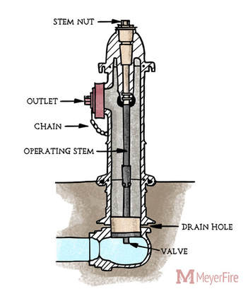 Bonnet The conical cap for the hydrant, or bonnet, holds the operating stem nut in place and protects the hydrant from mechanical damage and water penetration. Branch The branch pipe serving the hydrant from the city main is one restriction for the overall capacity of a hydrant. While older systems often connect hydrants with 4-inch branch pipe, a minimum of 6-inch pipe should be used to limit pressure loss and permit greater flow capacity. Our friction loss tool can be helpful in estimating loss through these pipes. Flange The flange at the base of the hydrant is the point of connection for the hydrant to the rest of the barrel. While the dimension from the bonnet to the flange of the hydrant is standard, the height of the flange becomes important during installation as it determines the height of the outlets. Because hydrants need to be quickly accessed during an active fire, hydrant outlets need to be installed tall enough to allow a full-revolution of a hydrant wrench from the lowest outlet. Hydrant Color Some jurisdictions paint hydrants or hydrant bonnets to identify the capacity of the hydrant. NFPA 291, the Recommended Practice for Fire Flow Testing and Marking of Hydrants, suggests hydrant colors as Red/Class C, Orange/Class B, Green/Class A, and Light Blue/Class AA for Less than 500 gpm, up to 1,000 gpm, up to 1,500 gpm, and 1,500 gpm and more, respectively (NFPA 291-2019 5.2.1.2). Outlets A traditional dry barrel fire hydrant contains three outlets: two 2 1/2-inch (65 mm) side outlets and a single 4 1/2-inch (115 mm) or 6-inch (150 mm) "pumper" outlet. The latter outlet gets its name as it is often the preferred choice for the fire department to connect and feed pumper trucks. The size and number of the outlets serve as one limit to the capacity of the hydrant. While the typical hydrant described above is the most common type, other combinations certainly exist - downtown St. Louis, for instance, have hydrants with only a single pumper outlet. Stem Nut The stem nut is the key to operating the valve within the hydrant. Typically shaped as a pentagon, the stem nut will turn the operating stem of the hydrant and raise the valve to an 'open' position when turned with a hydrant wrench. Thrust Block Unless mechanically restrained, thrust blocks serve as a way to distribute the hydraulic force of the pipe network into the soil. Our thrust block calculator can be helpful in sizing these blocks. Valve When in the 'open' position, the valve at the bottom of a dry barrel hydrant rises to plug drain holes and simultaneously permit water to fill the barrel of the hydrant. When in the 'closed' position, the valve lowers to block water passage and re-open drain holes at the bottom of the hydrant. These drain holes act as weeps which slowly drain the hydrant barrel and help prevent freezing. Follow the Movement
Get these free articles as they're written each week. Follow the movement & get a free sprinkler canopy & overhang requirements guide here: One of the popular aspects of fire sprinkler installations that is overwhelmingly familiar to fitters in the field yet something I hardly understood back as a new graduate is pipe connections. Today I'm breaking out some of the popular methods of joining steel pipe in fire sprinkler systems. Steel Pipe While copper, CPVC and PEX are listed for use in fire sprinkler systems (PEX is only for NFPA 13D systems), black steel pipe remains the most popular pipe material for commercial fire sprinkler applications, at least within the United States. For steel pipe, the primary means of connecting the pipe include threaded fittings, grooved fittings, plain-end compression fittings, flanged connections, and welding. Plain End Pipe Steel pipe when initially formed has flat cut, unpolished ends. This is generally referred to as plain end pipe. Plain end pipe can be connected by compression fittings or push-on fittings, which bite into the pipe to prevent separation. While popular for other building systems, use of plain end pipe and compression or push-on fittings are not used in sprinkler systems due to the relatively high pressures sprinkler systems experience. 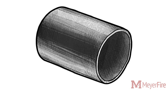 Threaded Pipe Perhaps the most common current method of joining fire sprinkler pipe for smaller pipe diameters, threaded pipe makes use of helical crests that screw into a female threaded fitting. To create threaded pipe, a plain-end pipe is cut with a threaded machine decreasing the thickness of the pipe wall. As a result, the areas remaining below and adjacent to the thread become weaker and more susceptible to corrosion breakthroughs with the thinner wall of pipe. 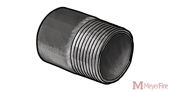 As compared to grooving or welding pipe, the pipe wall thickness must be thicker to accommodate the cut-in threads (ASME B1.20.1) for threaded pipe. NFPA 13 6.5.1.2 (2002-2016 Editions) addresses minimum pipe thicknesses for threaded pipe up to 300 psi, unless the pipe is separately listed for fire sprinkler use:
When connecting threaded pipe, joint compound or pipe tape is applied to the male thread to avoid water leakage. While threading larger pipe was common throughout the early to mid twentieth century, the weight of Schedule 40 pipe and difficulty of turning large diameter threaded pipe makes threading an uncommon choice for larger diameter sprinkler pipe today. Grooved Pipe Grooved pipe is a popular method of pipe joining invented by Victaulic with roots in both World Wars to deliver water and petroleum with faster, more reliable method of pipe connection. 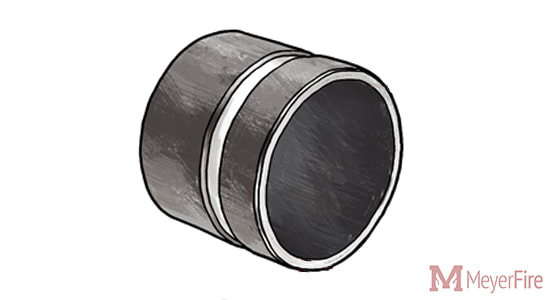 Grooved pipe is formed by either cutting into the pipe (cut groove) or by pressing an indentation into the pipe (roll groove). Cut groove pipe results in a lesser pipe thickness, weakening the pipe and also offering less protection against corrosion. Roll grooving, while keeping the pipe wall thickness, also poses issues in low-sloped dry and pre-action systems as the rolls on the interior side of the pipe create areas to trap water and create an air-water interface for corrosion to occur. 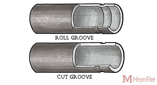 Grooved pipe has a number of inherent advantages. Smaller pipe thicknesses are permitted for grooved pipe, resulting in thinner pipe which makes transporting, carrying, and lifting into place easier. Minimum thicknesses for Grooved Pipe:
With thinner, lighter pipe and easy grooved coupling options, labor can be less difficult and significantly quicker. Welded & Flanged Pipe A less common but additional option for restraining pipe is welding. Pipe can be welded as an outlet - where a welding equipment cuts a hole in one pipe whereafter another pipe segment is held in place and the two are welded together. 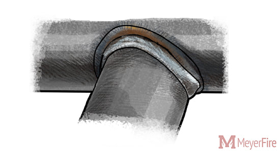 Welding has a few advantages - it can be (and often is) performed in a fabrication shop, does not require any additional fittings, and can allow for more custom pipe arrangements. For instance: a 4-inch x 4-inch x 1/2-inch outlet for a pressure gauge connection might be a special order reducing tee (ie: costly); as a welded outlet, it could be quickly and easily welded into place with the outlet easily threaded or grooved. Welding is not limited to outlets, however. "Slip-on flanges" can be welded to the hub side of the flange to a piece of pipe, allowing two flanged fittings to be bolted together with a gasket in-between. 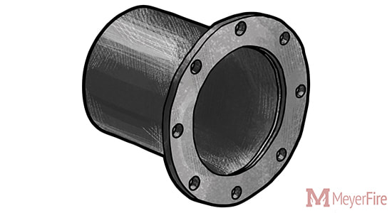 Flanged pipe and fittings are common around fire pump assemblies, as NFPA 20 annex material even notes that "flanges welded to pipe are preferred" despite screwed, flanged mechanical joints or other approved fittings are allowable (NFPA 20 2003-2007 5.13.2.1, 2010-2013 4.13.2, 2016 4.14.2, 2019 4.15.2).
Different installing contractors often have different preferences on fabricating pipe. Personally I've worked with some who prefer to have welded outlets along 21-foot lengths of pipe and groove as much as allowed for a job to use lighter, thinner pipe, including through branch piping. Others prefer some flexibility of threaded pipe to make quick changes in the field and provide a more traditional, tightly-connected threaded system. What do you commonly see? Does your team have preferences for fabrication methods? Discuss this here. Follow the Movement Get these articles, for free, once a week. Follow the movement for better fire protection here.
Last week I introduced a new Thrust Block Calculator and explored some of the concepts around the design and function of Thrust Blocks.
Expanded Calculator Here's the new expanded thrust block calculator. With similar inputs as before, we're now able to calculate the thrust block volume required, as well as determine the height and width required for the thrust block. Toolkit is Here Well it's here! The MeyerFire Toolkit is past a beta version and ready for you. 
Don't Get These Updates? You can subscribe to all the tools and resources we discuss and create by following the blog here: Join In
One fundamental aspect of fluid movement is thrust force, which is created when a flow path bends, tees, wyes, dead ends, or reduces. In order to counter the unbalanced forces that are created at these locations, the pipe and fittings must be mechanically restrained from separating, welded together, or otherwise fixed from movement.
Push-On Underground Joints One popular method of preventing pipe separation for underground pipe is gasketed push-on joints for underground pipe that do not have special locking devices, but permit pipe to be installed in any direction and at any point along the path. Role of Thrust Blocks In order to prevent the internal pressure from forcing the pipe and fittings to separate, blocking (or "thrust blocks") provide stability and allow the surrounding soil to accept the thrust force from the pipe assembly. Soil conditions vary in its ability to handle forces. Thrust blocks allow a narrow point force to be spread and distributed across larger areas of soil down to a pressure that the soil can bear. 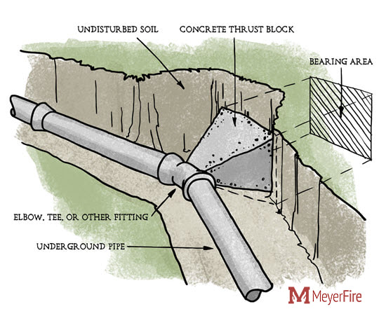
Thrust blocks take the point force created from the change in direction of the water (static and dynamic)
and distribute that force to the soil. The Calculator The tool below is an early part of a larger effort to determine the thrust block detailing. In the coming weeks, I would like to add block height, width, volume and visualizations to detail the parameters. Don't see the tool below? Click here. For those who work routinely with thrust block and their calculations under NFPA 13, what else could I add to this tool to be more useful? Comment here or email me at [email protected] if you have any ideas. The Toolkit - Launches Next Week The long-awaited Toolkit launches next week - complete with this and other tools in a downloadable software package. Be the office hero with quick and printable tools, as well as access to the Sprinkler Database and the ability to post questions to users on the Daily Discussion forum. Look out for news regarding the launch next week. Get More Like This If you don't already subscribe to these articles & resources, you can do so, for free, here: |

ALL-ACCESS
SUBSCRIBEGet Free Articles via Email:
+ Get calculators, tools, resources and articles
+ Get our PDF Flowchart for Canopy & Overhang Requirements instantly 
+ No spam
+ Unsubscribe anytime AUTHORJoe Meyer, PE, is a Fire Protection Engineer out of St. Louis, Missouri who writes & develops resources for Fire Protection Professionals. See bio here: About FILTERS
All
ARCHIVES
July 2024
|
 RSS Feed