
|
In January, suppression expert Bob Upson presented a webinar on frequently asked questions concerning standpipe systems out of NFPA 14 with NFSA's online teaching platform. If you work with standpipe systems regularly, I'd highly recommend it. One of the topics he discussed was a brief history of how both the International Building Code (IBC) and NFPA 14 (Standard for the Installation of Standpipe and Hose Systems) have changed over time between requiring standpipe hose connections on intermediate floor-level landings to floor-level landings. By floor-level landings, typically you would have a hose connection 3-5 feet above the floor level immediately at the landing upon entering an exit stair. To get to a hose connection on an intermediate-level landing, you would enter the stair and walk down a single flight of stairs to get to the next landing (typically opposite of the main floor level landing). I was interested in exploring this code history in a little more detail - so below is a compilation of the last 20 years of the IBC and NFPA 14 and where standpipe hose connections have been required by each code edition within exit stairs. 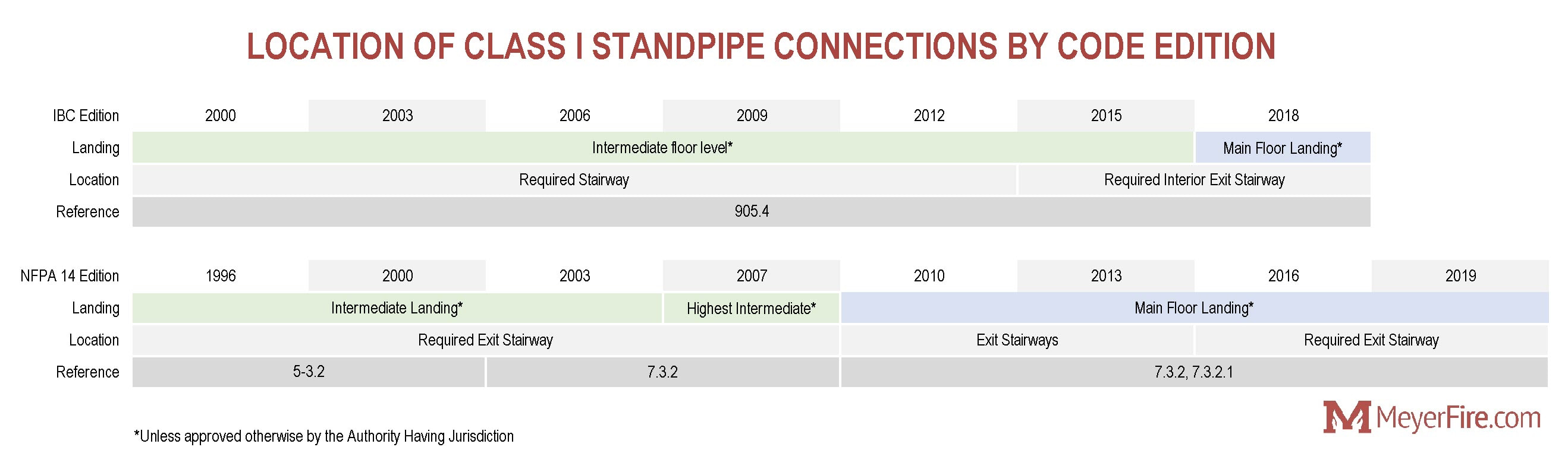 A summary of the code history of intermediate-floor-level landings versus floor-level landing requirements for standpipe systems across both the IBC and NFPA 14. Click to enlarge. It's important to note that while code prescribes one location (floor level or intermediate-level stair landings), every single code instance allows the opposite location to be used with approval from the Authority Having Jurisdiction. Next week I'll break out the implications for these requirements with some visuals and things to consider when designing for floor-level landings of intermediate-level landings. What challenges do you experience when designing for floor-level or intermediate-level landing hose connections? What advice would you offer? Comment and be part of the conversation here. Hope your week in fire protection is going well. Standpipes within stairs can be an important item to coordinate with the project architect, as the fix for the lack of coordination can be extremely difficult to accomplish in the field. This week I'm breaking down an enlarged floor plan detail for a standpipe hose connection within a stairwell. 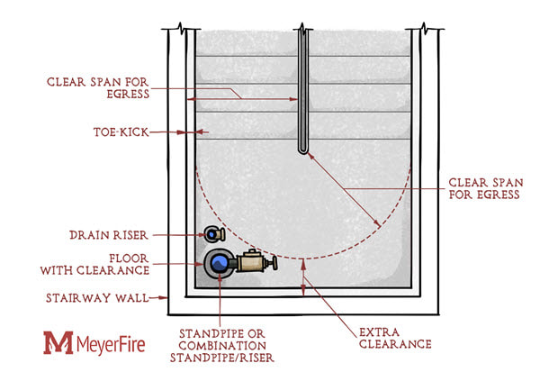 Avoiding the Egress Path The image above shows the clear span that's required to maintain clearance. How do you know the radius of this line? Just take the width of the stair, set the center of your arc to the edge of the stair, and draw your arc from one end of the stair to the other. This is an extension of the required egress of the stair to turn on the landing and move the other direction. Is it possible and allowed to locate small parts of the hose connection within this clear span? There could be a basis for it. In design I try to avoid any controversy by locating both the standpipe and those valve entirely outside of this egress path. Doing so may require a little extra space on the landing, but it is far better than finding out after the stair is constructed that you're short on space. Structural Conflicts A traditional new-construction stair will likely have support for the stairwell landing incorporated into the stair enclosure, or contain a beam across the landing where the landing meets the beginning of the stairs if it's a concrete stair. These new builds don't present too much of a challenge to coordinate with structure. However, for retrofits or stairs that do not simply jog back and forth, beware of beams that could run where you'd like to locate the standpipe connections. Core drilling a 4-inch to 10-inch hole through a concrete beam will not make you good friends with the structural engineer. Handle Clearance The hose connection is required to have 3-inches of clearance on all sides of the handle. (NFPA 14 2013-19 4.7.5) It's not enough to just stick your hand and start turning the valve, we have to remember that it's the firefighter's thermally insulated and rigid gloves that must turn the hose valve while the building is literally on fire. Giving 3-inches of clearance just feels like a minimally-nice gesture to thank your local first responder. Drain Riser Lastly, don't forget about the drain riser. If the standpipe includes pressure-reducing valves, these valves require testing and it's required to have a way to connect directly to an oversized drain riser that can handle the testing. This can be done with capped outlets on the drain riser that can accept a hose connection for testing. NFPA 14 provides guidance on sizing the drain riser in this scenario: 3-inch drain riser for 2-1/2-inch pressure reducing devices, a 2-inch riser for 1-1/2-inch pressure reducing devices, or sized large enough to handle the full flow from the largest pressure reducing device. (NFPA 14 20037.12, 2007-19 7.11.1) Know someone who might be interested in content like this? Please forward them a link. Want to get weekly articles like this yourself? Subscribe here. Hope your week is going very well. This week I'd like to open a short series on standpipes. Today's article is a basic overview of some basic requirements associated with standpipes used for fire suppression. 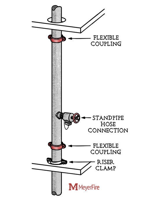 Basic components of a standpipe for fire suppression. Purpose Standpipes are used to support manual firefighting efforts by delivering water to hard-to-reach areas of a building. The intent of a standpipe system is to avoid having to distribute and connect hundreds of feet of hose for a single interior attack by firefighters. Hard-to-reach areas of a building aren't confined to one direction. Buildings which are very tall (highrises) or are deep underground, or are very wide by nature could all have portions of the building which would be difficult to reach. Applicable Codes & Standards In the US, the International Building Code (IBC) and International Fire Code (IFC) are often the first stop for standpipe requirements. While the two codes mirror each other, the International Building Code requires standpipes based on:
Once it has been determined whether a standpipe system is required or not, the IBC and IFC defer to NFPA 14 to prescribe how the system is to be installed. 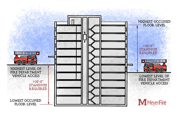 Class of Standpipes Standpipes can be classified in several areas. The first is the class of standpipe, which relates directly to the hose connection type and the intended user. Based on 1-1/2 inch hose failures and the associated testing that goes along with them, 1-1/2 inch hose stations are much less common today. I've found many situations with sprinklered buildings where hose stations have been removed as they are no longer required and are a burden for testing and maintenance. Here are the standpipe classifications, with Class I being by far the most common in the US today:
Types of Standpipe The other defining description for standpipe is when water is delivered, and at what relative pressure. Types of standpipes include:
Components of a Vertical Standpipe Standpipes are not always vertical standpipes, but for multi-story buildings they are the most prevalent and are the topic of discussion this week. Flexible Coupling
Isolation Valve
Penetration Clearance
Pressure Gauge
Riser Clamp
Standpipe Hose Connections
Want to follow the rest of this series, or know someone who might be interested? Subscribe here. What Project? When I first started in the industry I worked on a long line of high-end retail projects scattered across the United States. Six months after starting I got a question from a project manager about concealed space wood-structure sprinkler protection on a particular store in San Jose. San Jose? I was positive I never worked on a project in San Jose. A little digging later revealed I did in fact work on a small retail shop in San Jose. The only problem was that it looked just like the other 30 stores I had worked on in-between. Did I evaluate protection or even consider the combustible above-ceiling space? Did I discuss anything with the AHJ? No idea. I quickly realized that if I didn't take project-specific design notes I'd have no way of revisiting my thought process when a question inevitably arose later in the project. The Mad Man Ever since then, and not entirely due to my undiagnosed organization issues, I've been on a mad hunt to find the best way to record project notes in the cleanest and most insanely-quick process possible. For me it's partially about recording the design thought process, and partially about reminding myself about all the considerations that need to occur for a project. I can't say I've tried every method for project note taking, but I have used word templates, checklists, spreadsheets, OneNote files, linked databases, access databases, and the good old pen and paper. Important Pieces I have several goals when devising project notes for me and the staff I work with:
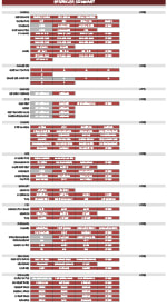
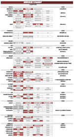
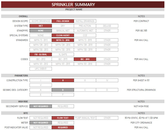 An example project design sheet (click to see full PDF) Latest Rendition Here's where I am now - an excel-based, single page note page where a quick "X" above a cell highlights the one below. If I know all of the information in a project, it can be filled out completely in less than 3 minutes. It can be a helpful accompaniment for sprinkler contractor clients when we're submitting a bid, or helpful notes to accompany a QC set of drawings. What Am I Missing? I'm sure your checklists and cheatsheets include a wide variety of considerations. In my attempt to better this one and incorporate the whole spreadsheet, what important elements am I missing? View PDFs below, and post your comments & feedback about important things to add here. Subscribe Find these conversations interesting? Forward to a friend or subscribe to these weekly posts here. If you've been following the blog for awhile, you might already know about the Toolkit that has really taken off lately. This past week I've incorporated some (great) user feedback and now have a new version to present: I've revamped the organization and it's FAR easier to navigate and use now. With a new main menu and crisp pages the Toolkit is FAR easier to navigate. Now you can get what you need, quickly. If you're already a subscriber to the Toolkit, use the download link below to get the latest version right now. No need for any new access codes - it just updates the Toolkit right over your current version. 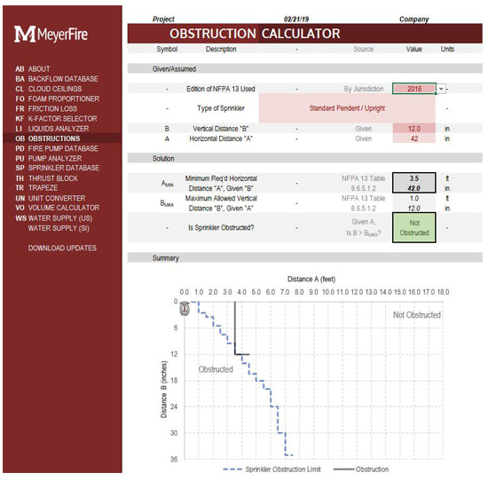 A clip of the latest version of the Sprinkler Obstruction Calculator on the MeyerFire Toolkit. What is the Toolkit, and what does it include? The MeyerFire Toolkit is a downloadable series of excel-based tools that allow fire protection designers, engineers and code authorities to quickly calculate a myriad of regular applications. With this tool you can save time with quick but powerful tools that you can save, PDF, or print. The Toolkit contains all of the tools you see on this website - plus the popular Fire Sprinkler Database - which is a live collection of all fire sprinklers on the market where you can sort and filter to see what products exist for your application, and then specify or design the ones that best match your design goals.  What's Next?
There's a few new additions to the Toolkit I hope to debut in the next couple weeks based on suggestions from users just like you. If you're an expert in fire flow calculations or water storage tank design and are interested in early testing, email me at jdmeyer@meyerfire.com. Subscribe If you know someone who might be interested in giving the Toolkit a try, email them about downloading it today. As always, you can subscribe to these weekly articles & resources here. This week we're covering a basic riser manifold configuration for wet-pipe fire sprinkler systems. This is not for a shotgun-style single riser, nor for a wet riser using an alarm check valve (we'll explore both of those later). If you haven't checked it out, there are great ongoing discussions (some of which covered these topics) on the MeyerFire Daily page here. 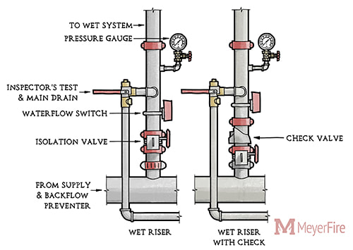 Overview Wet-pipe systems form the backbone of traditional fire sprinkler system design, comprising the most popular and most economical system type available. Here's the major components that go into a wet-pipe fire sprinkler assembly: Check Valve
FDC Connection
I receive feedback regularly from many users and observers - and I'm very grateful for both! Sprinkler Database Interest & Feedback One member recently reached out about the Sprinkler Database and said: "I appreciate all the work you’ve done on that site. The sprinkler database has helped tremendously when looking for specialty sprinklers, specifically available storage sprinkler is odd configurations!" It's a tool that is basic in premise but can save tons of time when you're looking to compare sprinklers, find a specific type of sprinkler, or see if a solution exists for your specific problem. Here's a quick overview Fire Pump Database With the interest and feedback from the Sprinkler Database, it was only a matter of time before I expanded this into other areas. You may already have seen the Backflow Database, but now we have a beta version of a Fire Pump Database. With the fire pump database you can now search for fire pumps of various configurations, drivers, sizes, and then instantly link to CAD and Revit models, performance curves, website links, product data, and dimensions. The current beta version includes AC, Armstrong, and Aurora Fire Pumps. All-inclusive Toolkit members can log in and use the database now.  Know a Contact for Patterson or Peerless? If you work for or know a great contact for Patterson Fire Pumps and Peerless Fire Pumps, please let me know their contact information. I'm looking to partner with both of these companies to also help connect users to their products. Toolkit Sale Through November 30th Interested in getting the Toolkit and access to all of our tools? Join between now and Friday the 30th for $30 off your first year's subscription. Just use coupon code CYBER18 when you checkout here before Friday November 30th. Lastly, if you're in the US, I hope you have a great Thanksgiving!
First, a big thank you to those who commented and emailed ideas and topics that contributed to the latest tool for this site - the Trapeze Calculator.
Quick Calc With only a few "knowns" (pipe diameter and schedule, and distances to nearest structure), you can now quickly calculate the section modulus that's required, visit options for the trapeze bar, and see these options schematically in a to-scale detail. Multiple Pipes Have multiple pipes on a trapeze? Calculate the section modulus required for each, add the two moduli together, and simply override the Section Modulus Required value below to see your options. Get CAD Details Want a CAD version of the detail? Sure thing - the downloadable All-Access Toolkit allows you to save and print these calculations as PDFs, which can then be imported directly into AutoCAD and use the ALIGN function to scale it to your drawing. Toolkit Users Already a Toolkit user? Install the latest version from your dashboard to get the updates to this tool. No new activation code is necessary. Don't see the tool below? Try it out here - This site is all about finding ways to help you be the office hero with quick and helpful fire protection tools. Get these weekly articles straight to your inbox by subscribing here.
First, a huge thank you to everyone who's expressed interest and purchased the Toolkit - I very much appreciate the fantastic response to the launch over the last three weeks!
It's a short post this week - I've been developing a Trapeze Hanger tool that sizes and schematically details trapeze hangers. This will likely be the first of three posts while developing this tool. Questions for you at this point in time: (1) What other possible standard trapeze materials do you use that could be helpful as part of this tool? (2) What would you like to see shown in the detail? (3) If the detail could be easily translated to AutoCAD from this calculator, could it be something helpful for your projects? If so, what would you want shown and identified? Click here to test and comment on the Trapeze Hanger tool, thanks in advance! Know someone who might be interested in resources or articles like this? Forward to a friend. Don't get these articles sent weekly to your inbox? Subscribe here. One of the popular aspects of fire sprinkler installations that is overwhelmingly familiar to fitters in the field yet something I hardly understood back as a new graduate is pipe connections. Today I'm breaking out some of the popular methods of joining steel pipe in fire sprinkler systems. Steel Pipe While copper, CPVC and PEX are listed for use in fire sprinkler systems (PEX is only for NFPA 13D systems), black steel pipe remains the most popular pipe material for commercial fire sprinkler applications, at least within the United States. For steel pipe, the primary means of connecting the pipe include threaded fittings, grooved fittings, plain-end compression fittings, flanged connections, and welding. Plain End Pipe Steel pipe when initially formed has flat cut, unpolished ends. This is generally referred to as plain end pipe. Plain end pipe can be connected by compression fittings or push-on fittings, which bite into the pipe to prevent separation. While popular for other building systems, use of plain end pipe and compression or push-on fittings are not used in sprinkler systems due to the relatively high pressures sprinkler systems experience. 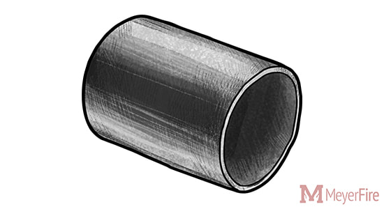 Threaded Pipe Perhaps the most common current method of joining fire sprinkler pipe for smaller pipe diameters, threaded pipe makes use of helical crests that screw into a female threaded fitting. To create threaded pipe, a plain-end pipe is cut with a threaded machine decreasing the thickness of the pipe wall. As a result, the areas remaining below and adjacent to the thread become weaker and more susceptible to corrosion breakthroughs with the thinner wall of pipe. 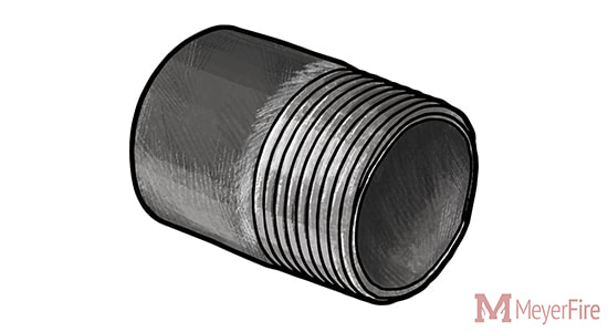 As compared to grooving or welding pipe, the pipe wall thickness must be thicker to accommodate the cut-in threads (ASME B1.20.1) for threaded pipe. NFPA 13 6.5.1.2 (2002-2016 Editions) addresses minimum pipe thicknesses for threaded pipe up to 300 psi, unless the pipe is separately listed for fire sprinkler use:
When connecting threaded pipe, joint compound or pipe tape is applied to the male thread to avoid water leakage. While threading larger pipe was common throughout the early to mid twentieth century, the weight of Schedule 40 pipe and difficulty of turning large diameter threaded pipe makes threading an uncommon choice for larger diameter sprinkler pipe today. Grooved Pipe Grooved pipe is a popular method of pipe joining invented by Victaulic with roots in both World Wars to deliver water and petroleum with faster, more reliable method of pipe connection. 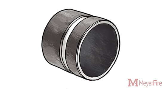 Grooved pipe is formed by either cutting into the pipe (cut groove) or by pressing an indentation into the pipe (roll groove). Cut groove pipe results in a lesser pipe thickness, weakening the pipe and also offering less protection against corrosion. Roll grooving, while keeping the pipe wall thickness, also poses issues in low-sloped dry and pre-action systems as the rolls on the interior side of the pipe create areas to trap water and create an air-water interface for corrosion to occur. 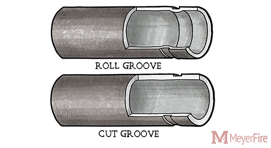 Grooved pipe has a number of inherent advantages. Smaller pipe thicknesses are permitted for grooved pipe, resulting in thinner pipe which makes transporting, carrying, and lifting into place easier. Minimum thicknesses for Grooved Pipe:
With thinner, lighter pipe and easy grooved coupling options, labor can be less difficult and significantly quicker. Welded & Flanged Pipe A less common but additional option for restraining pipe is welding. Pipe can be welded as an outlet - where a welding equipment cuts a hole in one pipe whereafter another pipe segment is held in place and the two are welded together. 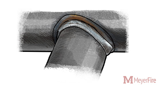 Welding has a few advantages - it can be (and often is) performed in a fabrication shop, does not require any additional fittings, and can allow for more custom pipe arrangements. For instance: a 4-inch x 4-inch x 1/2-inch outlet for a pressure gauge connection might be a special order reducing tee (ie: costly); as a welded outlet, it could be quickly and easily welded into place with the outlet easily threaded or grooved. Welding is not limited to outlets, however. "Slip-on flanges" can be welded to the hub side of the flange to a piece of pipe, allowing two flanged fittings to be bolted together with a gasket in-between. 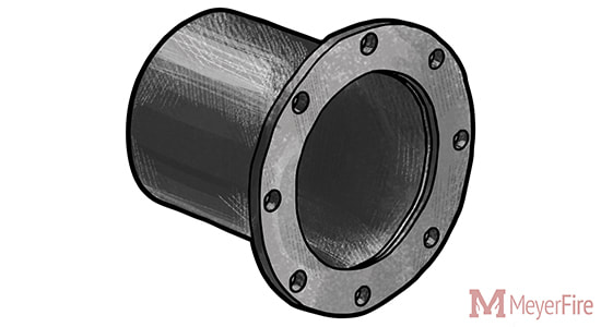 Flanged pipe and fittings are common around fire pump assemblies, as NFPA 20 annex material even notes that "flanges welded to pipe are preferred" despite screwed, flanged mechanical joints or other approved fittings are allowable (NFPA 20 2003-2007 5.13.2.1, 2010-2013 4.13.2, 2016 4.14.2, 2019 4.15.2).
Different installing contractors often have different preferences on fabricating pipe. Personally I've worked with some who prefer to have welded outlets along 21-foot lengths of pipe and groove as much as allowed for a job to use lighter, thinner pipe, including through branch piping. Others prefer some flexibility of threaded pipe to make quick changes in the field and provide a more traditional, tightly-connected threaded system. What do you commonly see? Does your team have preferences for fabrication methods? Discuss this here. Follow the Movement Get these articles, for free, once a week. Follow the movement for better fire protection here. |

ALL-ACCESS
SUBSCRIBEGet Free Articles via Email:
+ Get calculators, tools, resources and articles
+ Get our PDF Flowchart for Canopy & Overhang Requirements instantly 
+ No spam
+ Unsubscribe anytime AUTHORJoe Meyer, PE, is a Fire Protection Engineer out of St. Louis, Missouri who writes & develops resources for Fire Protection Professionals. See bio here: About FILTERS
All
ARCHIVES
April 2024
|
 RSS Feed