
|
One of the popular aspects of fire sprinkler installations that is overwhelmingly familiar to fitters in the field yet something I hardly understood back as a new graduate is pipe connections. Today I'm breaking out some of the popular methods of joining steel pipe in fire sprinkler systems. Steel Pipe While copper, CPVC and PEX are listed for use in fire sprinkler systems (PEX is only for NFPA 13D systems), black steel pipe remains the most popular pipe material for commercial fire sprinkler applications, at least within the United States. For steel pipe, the primary means of connecting the pipe include threaded fittings, grooved fittings, plain-end compression fittings, flanged connections, and welding. Plain End Pipe Steel pipe when initially formed has flat cut, unpolished ends. This is generally referred to as plain end pipe. Plain end pipe can be connected by compression fittings or push-on fittings, which bite into the pipe to prevent separation. While popular for other building systems, use of plain end pipe and compression or push-on fittings are not used in sprinkler systems due to the relatively high pressures sprinkler systems experience. 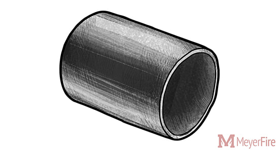 Threaded Pipe Perhaps the most common current method of joining fire sprinkler pipe for smaller pipe diameters, threaded pipe makes use of helical crests that screw into a female threaded fitting. To create threaded pipe, a plain-end pipe is cut with a threaded machine decreasing the thickness of the pipe wall. As a result, the areas remaining below and adjacent to the thread become weaker and more susceptible to corrosion breakthroughs with the thinner wall of pipe. 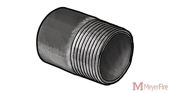 As compared to grooving or welding pipe, the pipe wall thickness must be thicker to accommodate the cut-in threads (ASME B1.20.1) for threaded pipe. NFPA 13 6.5.1.2 (2002-2016 Editions) addresses minimum pipe thicknesses for threaded pipe up to 300 psi, unless the pipe is separately listed for fire sprinkler use:
When connecting threaded pipe, joint compound or pipe tape is applied to the male thread to avoid water leakage. While threading larger pipe was common throughout the early to mid twentieth century, the weight of Schedule 40 pipe and difficulty of turning large diameter threaded pipe makes threading an uncommon choice for larger diameter sprinkler pipe today. Grooved Pipe Grooved pipe is a popular method of pipe joining invented by Victaulic with roots in both World Wars to deliver water and petroleum with faster, more reliable method of pipe connection. 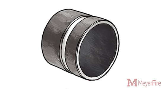 Grooved pipe is formed by either cutting into the pipe (cut groove) or by pressing an indentation into the pipe (roll groove). Cut groove pipe results in a lesser pipe thickness, weakening the pipe and also offering less protection against corrosion. Roll grooving, while keeping the pipe wall thickness, also poses issues in low-sloped dry and pre-action systems as the rolls on the interior side of the pipe create areas to trap water and create an air-water interface for corrosion to occur. 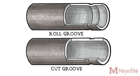 Grooved pipe has a number of inherent advantages. Smaller pipe thicknesses are permitted for grooved pipe, resulting in thinner pipe which makes transporting, carrying, and lifting into place easier. Minimum thicknesses for Grooved Pipe:
With thinner, lighter pipe and easy grooved coupling options, labor can be less difficult and significantly quicker. Welded & Flanged Pipe A less common but additional option for restraining pipe is welding. Pipe can be welded as an outlet - where a welding equipment cuts a hole in one pipe whereafter another pipe segment is held in place and the two are welded together. 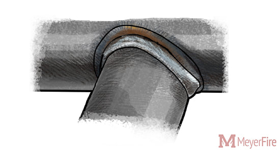 Welding has a few advantages - it can be (and often is) performed in a fabrication shop, does not require any additional fittings, and can allow for more custom pipe arrangements. For instance: a 4-inch x 4-inch x 1/2-inch outlet for a pressure gauge connection might be a special order reducing tee (ie: costly); as a welded outlet, it could be quickly and easily welded into place with the outlet easily threaded or grooved. Welding is not limited to outlets, however. "Slip-on flanges" can be welded to the hub side of the flange to a piece of pipe, allowing two flanged fittings to be bolted together with a gasket in-between. 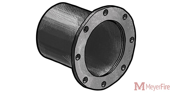 Flanged pipe and fittings are common around fire pump assemblies, as NFPA 20 annex material even notes that "flanges welded to pipe are preferred" despite screwed, flanged mechanical joints or other approved fittings are allowable (NFPA 20 2003-2007 5.13.2.1, 2010-2013 4.13.2, 2016 4.14.2, 2019 4.15.2).
Different installing contractors often have different preferences on fabricating pipe. Personally I've worked with some who prefer to have welded outlets along 21-foot lengths of pipe and groove as much as allowed for a job to use lighter, thinner pipe, including through branch piping. Others prefer some flexibility of threaded pipe to make quick changes in the field and provide a more traditional, tightly-connected threaded system. What do you commonly see? Does your team have preferences for fabrication methods? Discuss this here. Follow the Movement Get these articles, for free, once a week. Follow the movement for better fire protection here.
Nimal Tissa Wijetunga
8/1/2018 12:46:29 am
Dear Sir,
Joe Meyer
8/5/2018 06:35:45 am
Hi Nimal,
Michael J. Agri Jr.
8/5/2018 02:21:11 pm
Nice, clear, concise piece.
Chuck U Farly
8/5/2018 09:11:19 pm
You do realize that schedule 10 grooved in 2 1/2” and larger sizes has been used for many years right? 10/15/2018 07:05:44 am
This is something interesting.I found this article very informative . I am glad that I came across such an article.You have very nicely explained about it in a detailed manner.Keep posting such article. 3/4/2019 01:00:50 pm
I ask this only to satisfy my own curious nature. 5/28/2019 05:17:31 am
Dear Sir, 6/11/2019 01:38:38 pm
It's good to know that grooved pipe is formed by cutting into the pipe. My brother has been wondering how groove pipe is made for a while now. I'll pass this information along to him so that he's aware of how it's made. Comments are closed.
|

ALL-ACCESS
SUBSCRIBEGet Free Articles via Email:
+ Get calculators, tools, resources and articles
+ Get our PDF Flowchart for Canopy & Overhang Requirements instantly 
+ No spam
+ Unsubscribe anytime AUTHORJoe Meyer, PE, is a Fire Protection Engineer out of St. Louis, Missouri who writes & develops resources for Fire Protection Professionals. See bio here: About FILTERS
All
ARCHIVES
July 2024
|
 RSS Feed