MeyerFire
  • Blog
  • Forum
  • TOOLKIT
    • ALL TOOLS
    • BUY THE TOOLKIT
  • UNIVERSITY
    • ALL COURSES
    • JOIN THE UNIVERSITY
  • PE Exam
    • PE Forum & Errata
    • PE Store
    • PE Tools
    • PE PREP SERIES
    • PE Old Questions
  • LOGIN
    • TOOLKIT-ONLY LOGIN
    • UNIVERSITY LOGIN
  • STORE
  • OUR CAUSE
    • ABOUT MEYERFIRE
    • JOB OPENINGS
    • BECOME AN INSTRUCTOR
    • HELP/SUPPORT
Picture

Methods of Connecting Fire Sprinkler Pipe

7/18/2018

 
One of the popular aspects of fire sprinkler installations that is overwhelmingly familiar to fitters in the field yet something I hardly understood back as a new graduate is pipe connections. Today I'm breaking out some of the popular methods of joining steel pipe in fire sprinkler systems.

Steel Pipe
While copper, CPVC and PEX are listed for use in fire sprinkler systems (PEX is only for NFPA 13D systems), black steel pipe remains the most popular pipe material for commercial fire sprinkler applications, at least within the United States.

For steel pipe, the primary means of connecting the pipe include threaded fittings, grooved fittings, plain-end compression fittings, flanged connections, and welding.

Plain End Pipe
Steel pipe when initially formed has flat cut, unpolished ends. This is generally referred to as plain end pipe. 

Plain end pipe can be connected by compression fittings or push-on fittings, which bite into the pipe to prevent separation. While popular for other building systems, use of plain end pipe and compression or push-on fittings are not used in sprinkler systems due to the relatively high pressures sprinkler systems experience.
Black Steel Plain End Pipe
Threaded Pipe
​Perhaps the most common current method of joining fire sprinkler pipe for smaller pipe diameters, threaded pipe makes use of helical crests that screw into a female threaded fitting.

To create threaded pipe, a plain-end pipe is cut with a threaded machine decreasing the thickness of the pipe wall. As a result, the areas remaining below and adjacent to the thread become weaker and more susceptible to corrosion breakthroughs with the thinner wall of pipe.
Threaded Fire Sprinkler Pipe

​As compared to grooving or welding pipe, the pipe wall thickness must be thicker to accommodate the cut-in threads (ASME B1.20.1) for threaded pipe. NFPA 13 6.5.1.2 (2002-2016 Editions) addresses minimum pipe thicknesses for threaded pipe up to 300 psi, unless the pipe is separately listed for fire sprinkler use:
Pipe Diameter
Minimum Pipe Thickness for Threaded Pipe
Basis
6-inch and smaller
Schedule 40
NFPA 13 2002-2016 6.3.3
8-inch and greater
Schedule 30
NFPA 13 2002-2016 6.3.3
When connecting threaded pipe, joint compound or pipe tape is applied to the male thread to avoid water leakage. 

While threading larger pipe was common throughout the early to mid twentieth century, the weight of Schedule 40 pipe and difficulty of turning large diameter threaded pipe makes threading an uncommon choice for larger diameter sprinkler pipe today.

Grooved Pipe
Grooved pipe is a popular method of pipe joining invented by Victaulic with roots in both World Wars to deliver water and petroleum with faster, more reliable method of pipe connection. 
Grooved Fire Sprinkler Pipe

Grooved pipe is formed by either cutting into the pipe (cut groove) or by pressing an indentation into the pipe (roll groove).

Cut groove pipe results in a lesser pipe thickness, weakening the pipe and also offering less protection against corrosion.

Roll grooving, while keeping the pipe wall thickness, also poses issues in low-sloped dry and pre-action systems as the rolls on the interior side of the pipe create areas to trap water and create an air-water interface for corrosion to occur.
​
Roll vs Cut Groove Fire Sprinkler Pipe

Grooved pipe has a number of inherent advantages. Smaller pipe thicknesses are permitted for grooved pipe, resulting in thinner pipe which makes transporting, carrying, and lifting into place easier. Minimum thicknesses for Grooved Pipe: 
Pipe Diameter
Minimum Pipe Thickness
​for Cut Grooved Pipe
Basis
6-inch and smaller
Schedule 40
NFPA 13 2002-2016 6.3.3
8-inch and larger
Schedule 30
NFPA 13 2002-2016 6.3.3
Pipe Diameter
Minimum Pipe Thickness
​for Roll Grooved Pipe
Basis
5-inch and smaller
Schedule 10
NFPA 13 2002-2016 6.3.2
6-inch
0.134 in.
NFPA 13 2002-2016 6.3.2
8-inch and 10-inch
​0.188 in.
NFPA 13 2002-2016 6.3.2
12-inch
0.330 in.
NFPA 13 2002-2016 6.3.2

With thinner, lighter pipe and easy grooved coupling options, labor can be less difficult and significantly quicker.

Welded & Flanged Pipe
A less common but additional option for restraining pipe is welding. Pipe can be welded as an outlet - where a welding equipment cuts a hole in one pipe whereafter another pipe segment is held in place and the two are welded together.
Welded Fire Sprinkler Pipe

Welding has a few advantages - it can be (and often is) performed in a fabrication shop, does not require any additional fittings, and can allow for more custom pipe arrangements.

For instance: a 4-inch x 4-inch x 1/2-inch outlet for a pressure gauge connection might be a special order reducing tee (ie: costly); as a welded outlet, it could be quickly and easily welded into place with the outlet easily threaded or grooved.

Welding is not limited to outlets, however. "Slip-on flanges" can be welded to the hub side of the flange to a piece of pipe, allowing two flanged fittings to be bolted together with a gasket in-between.
​
Flanged Fire Sprinkler Pipe

Flanged pipe and fittings are common around fire pump assemblies, as NFPA 20 annex material even notes that "flanges welded to pipe are preferred" despite screwed, flanged mechanical joints or other approved fittings are allowable (NFPA 20 2003-2007 5.13.2.1, 2010-2013 4.13.2, 2016 4.14.2, 2019 4.15.2).
Pipe Diameter
Minimum Pipe Thickness
​for Welded Pipe
Basis
5-inch and smaller
Schedule 10
NFPA 13 2002-2016 6.3.2
6-inch
0.134 in.
NFPA 13 2002-2016 6.3.2
8-inch and 10-inch
​0.188 in.
NFPA 13 2002-2016 6.3.2
12-inch
0.330 in.
NFPA 13 2002-2016 6.3.2

Different installing contractors often have different preferences on fabricating pipe. Personally I've worked with some who prefer to have welded outlets along 21-foot lengths of pipe and groove as much as allowed for a job to use lighter, thinner pipe, including through branch piping. Others prefer some flexibility of threaded pipe to make quick changes in the field and provide a more traditional, tightly-connected threaded system.

What do you commonly see? Does your team have preferences for fabrication methods? Discuss this here.

Follow the Movement
Get these articles, for free, once a week. Follow the movement for better fire protection here.

Flow Test Reports and the N^1.85 Supply Graph

4/11/2018

 
A few weeks ago I received a call from a sprinkler contractor who needed to provide a water supply graph for a flow test he conducted.

I had a canned sheet I had developed for my own flow tests, but it was a basic graph that showed a curve and didn't match the traditional N^1.85 hydraulic graphs common for water supply curves. Since then I've tinkered and come up with an accurate chart that takes flow test input values, calculates total flow and draws the curve along the N^1.85 chart.

Picture

​The N^1.85 chart is particularly useful for fire suppression systems because the Hazen-Williams formula is based on the relationship that pressure relates to flow to the 1.85th power.

Picture

Take a look at the N1.85 Water Supply Curve tool here and let me know what you think in the comment section below.


Download this Tool

​When the x-axis, or the hydraulic flow is then scaled to the 1.85th power, hydraulic curves become straight lines which becomes easier to graph and compare. Prior to everyone carrying a computer in their pocket, these graphs were likely much easier to use for summaries and comparisons.

The water supply information is what is provided as part of a two-hydrant flow test. The design input information would be the system demand side and can be used for quick comparisons.

Personally, I only use this setup for flow test reports and water supply comparisons. Fire sprinkler hydraulic calculation software takes care of the graphs and outputs I need after I've completed the hydraulic calculations.

On a side note, I've had several people ask about getting access to all of the tools I've created to use on their own computer with the ability to produce printable output for record keeping. Thanks again to those who asked - these are available now as part of the MeyerFire Toolkit - a collection of all of our quick-hitting tools. The Toolkit is also included as part of MeyerFire University at no additional cost.

Don't get these free weekly articles? Subscribe here.  My goal with creating this website and tools is to support those who want to create great fire protection.

A Breakout of a Floor Control Riser Assembly

9/16/2016

 
Today we're breaking into floor control assemblies. The following is a full arrangement for a combination standpipe/sprinkler riser where high pressures necessitate a pressure reducing valve at each level.
Picture
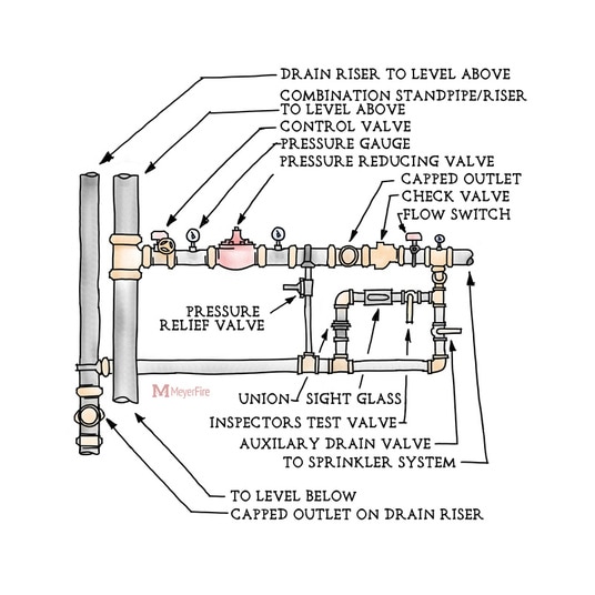
While every element in this specific arrangement is certainly not a necessity on every project, here's some considerations that go into the requirements and considerations for a layout like this:
Auxiliary Drain Valve
  • Permits faster draining of system (as opposed to only draining inspector's test valve)
Capped Outlets
  • Optionally included for testing of Pressure Reducing Valves, when provided (see Pressure Reducing Valve Testing below)
Check Valve
  • Can help reduce false waterflow alarms on floor where sprinklers have not activated (NFPA 13 2007-2016 Section A.8.17.1.6)
  • Required for a combined standpipe/sprinkler system (NFPA 13 2007-2016 Section 8.17.5.2.2(1))
Drain Pipe
  • Size: 3/4 inch for 2 inch system pipe, 1-1/4 inch for 2-1/2 - 3-1/2 inch system pipe, or 2 inch for 4 inch system pipe (NFPA 13 2002 Table 8.15.2.4.2, 2007-2016 Table 8.16.2.4.2)
Drain Valve
  • Minimum Size: 3/4 inch for 5-50 gallon system, 1 inch for 50+ gallon system (NFPA 13 2002 Section 8.15.2.5.2, 2007-2016 Section 8.16.2.5.2)
Drain Riser
  • Discharge: must be to outside or drain capable of handling the flow (NFPA 13 2002 Section 8.15.2.4.4, 2007-2016 Section 8.16.2.4.4)
  • Size: Must be at least one pipe size larger than the largest drain connection tying into it (NFPA 13 2002 Section 8.15.2.4.7, 2007-2013 Section 8.16.2.4.7, 2016 Section 8.16.2.4.8)
  • Size with PRV: When serving a Pressure Reducing Valve, the drain, drain connection, and drain piping shall be sized to permit the greatest system demand by the Pressure Reducing Valve (NFPA 13 2002 Section 8.15.2.4.5, 2007-2016 Section 8.16.2.4.5)
Height of Lowest Element
  • Objects cannot be more than 4 inches off of a wall unless they are more than 80 inches above the finished floor (ADA 2010 Section 307.2)
Inspector's Test
  • Accessible: Must be accessible (NFPA 13 2002 Section 8.16.4, 2007-2016 Section 8.17.4)
  • Discharge: Must discharge outside or to a drain capable of handling flow (NFPA 13 2002 Section 8.16.4, 2007-2016 Section 8.17.4)
  • Downstream of waterflow alarm (NFPA 13 2002 Section 8.16.4, 2007-2016 Section 8.17.4)
  • Orifice: Must have smooth bore, corrosion-resistant orifice with flow equal to or less than one sprinkler orifice on each system (NFPA 13 2002 Section 8.16.4, 2007-2016 Section 8.17.4)
​Pressure Gauge
  • Required at each floor control valve (NFPA 13 2002 Section 8.16.3.1, 2007-2016 8.17.3.1)
  • Must have a limit at least twice the system normal working pressure (NFPA 13 2002 8.16.3.1, 2007-2016 8.17.3.3)
​Pressure Reducing Valve (PRV)
  • Provided to reduce the system pressure such that the working pressure will not exceed a standard 175 PSI listed pressure of the sprinklers, piping, and fittings. PRVs can also be used to limit the system pressure to higher amounts when pressures are allowed to exceed 175 PSI.
  • Not required by code, and some have found PRVs to be prone to failure and difficult to test.
​Pressure Reducing Valve (PRV) Testing
  • Inspected: must be quarterly (NFPA 25 2014 Section 13.5.1.1)
  • Tested: must be partially tested annually (NFPA 25 2014 Section 5.1.3), and fully flowed every 5 years (NFPA 25 2014 Section 13.5.1.2)
  • Full flow testing in place: requires pressure gauge on inlet and outlet side of PRV, takes flow measurement using a pitot tube or flowmeter, discharging through the roof manifold on building exterior or through capped outlets provided for testing (NFPA 25 2014 13.5.1.2)
Riser 
  • Control Valve for entire riser: Required to permit isolating a riser without interrupting other systems (NFPA 13 2002 Section 8.16.5.2.2(3), 2007-2016 Section 8.17.5.2.2(3))
  • Size: Minimum 4 inch, unless hydraulically calculated to permit smaller size (NFPA 13 2002 Section 8.16.5.2.2(2), 2007-2016 Section 8.17.5.2.2(2)).
Sight Glass
  • Enables easy verification of water flow for inspector's test.
Supervisory Switches
  • Must be tested semiannually (NFPA 25 2014 Section 13.3.3.5.1)
​Union
  • Provided to permit exact orifice size of sprinkler for waterflow switch testing.
​Valve (Floor Control Valve)
  • Accessible (NFPA 13 2007 A.8.16.1.1.1)
  • Electrically supervised or locked (NFPA 25 2014 13.3.1.4)
  • Signage must be provided (NFPA 25 2014 13.3.1)
  • Tested: annually (NFPA 25 2014 Section 13.3.3.1)
Waterflow Switch
  • Tested: quarterly (NFPA 13 2002 Table A.18.1, 2007-2010 Table A.26.1, 2013-2016 Table A.27.1)
Want to see more like this? Subscribe to our Blog.
Forward>>
    Picture
    Why Sponsor?

    ALL-ACCESS

    Picture
    GET THE TOOLKIT

    SUBSCRIBE

    Get Free Articles via Email:
    + Get calculators, tools, resources and articles
    + Get our PDF Flowchart for Canopy & Overhang Requirements instantly
    Picture
    + No spam
    ​+ Unsubscribe anytime
    I'm Interested In:

    AUTHOR

    Joe Meyer, PE, is a Fire Protection Engineer out of St. Louis, Missouri who writes & develops resources for Fire Protection Professionals. See bio here: About


    FILTERS

    All
    Announcements
    Author Jocelyn Sarrantonio PE
    Book Review
    Calculators
    Career
    Course
    Delegated Design
    Design Challenge
    Detail Critique
    Fire Alarm
    Fire Events
    Fire Suppression
    Flammable & Combustible Liquids
    Flexible Drops
    Floor Control Valve
    Life Safety
    News
    NICET
    Passive Fire Protection
    PE Exam
    Perspective
    Pick A Part
    Pick-A-Part
    Products
    Site Updates
    Special Hazards
    Specifications
    Sprinkler Systems
    Standpipes
    Tools
    Videos


    ARCHIVES

    December 2025
    November 2025
    October 2025
    September 2025
    August 2025
    July 2025
    June 2025
    May 2025
    April 2025
    January 2025
    November 2024
    October 2024
    September 2024
    August 2024
    July 2024
    June 2024
    May 2024
    April 2024
    March 2024
    February 2024
    January 2024
    December 2023
    November 2023
    October 2023
    September 2023
    August 2023
    July 2023
    June 2023
    May 2023
    April 2023
    March 2023
    January 2023
    December 2022
    November 2022
    October 2022
    September 2022
    August 2022
    May 2022
    April 2022
    March 2022
    February 2022
    January 2022
    November 2021
    October 2021
    September 2021
    August 2021
    July 2021
    June 2021
    May 2021
    April 2021
    March 2021
    February 2021
    December 2020
    November 2020
    October 2020
    August 2020
    July 2020
    June 2020
    May 2020
    April 2020
    March 2020
    February 2020
    January 2020
    December 2019
    November 2019
    October 2019
    September 2019
    August 2019
    July 2019
    June 2019
    May 2019
    April 2019
    March 2019
    February 2019
    January 2019
    December 2018
    November 2018
    October 2018
    September 2018
    August 2018
    July 2018
    June 2018
    May 2018
    April 2018
    March 2018
    February 2018
    January 2018
    December 2017
    November 2017
    October 2017
    September 2017
    August 2017
    July 2017
    May 2017
    April 2017
    September 2016
    August 2016
    July 2016
    June 2016
    July 2015
    June 2015
    May 2015

    RSS Feed

Picture
​Home
Our Cause
The Blog
The Forum
PE Exam Prep
The Toolkit

MeyerFire University
​Pricing
Login
​Support
Contact Us
Picture

MeyerFire.com is a startup community built to help fire protection professionals shine.
Our goal is to improve fire protection practices worldwide. We promote the industry by creating helpful tools and resources, and by bringing together industry professionals to share their expertise.

​MeyerFire, LLC is a NICET Recognized Training Provider and International Code Council Preferred Education Provider.

All text, images, and media ​Copyright © 2016-2025 MeyerFire, LLC

We respect your privacy and personal data. See our Privacy Policy and Terms of Service. 
The views, opinions, and information found on this site represent solely the author and do not represent the opinions of any other party, nor does the presented material assume responsibility for its use. Fire protection and life safety systems constitute a critical component for public health and safety and you should consult with a licensed professional for proper design and code adherence.

Discussions are solely for the purpose of peer review and the exchange of ideas. All comments are reviewed. Comments which do not contribute, are not relevant, are spam, or are disrespectful in nature may be removed. Information presented and opinions expressed should not be relied upon as a replacement for consulting services. Some (not all) outbound links on this website, such as Amazon links, are affiliate-based where we receive a small commission for orders placed elsewhere.

  • Blog
  • Forum
  • TOOLKIT
    • ALL TOOLS
    • BUY THE TOOLKIT
  • UNIVERSITY
    • ALL COURSES
    • JOIN THE UNIVERSITY
  • PE Exam
    • PE Forum & Errata
    • PE Store
    • PE Tools
    • PE PREP SERIES
    • PE Old Questions
  • LOGIN
    • TOOLKIT-ONLY LOGIN
    • UNIVERSITY LOGIN
  • STORE
  • OUR CAUSE
    • ABOUT MEYERFIRE
    • JOB OPENINGS
    • BECOME AN INSTRUCTOR
    • HELP/SUPPORT